
In the "Spotlight"
See and enjoy the calm night-air conditions
by John Sabini
This application will allow you to fly safely at night and can be used in virtually any size FF, CL, or RC model. You simply adjust the system as necessary. With people's crazy work schedules, not to mention the fact that winds are usually calmer at night, this may turn out to be a new trend.
"Honey, let's go out tonight! We'll have a night out on the town—well, at the local flying field, that is."
When it was announced that there would be a nighttime competition at the Extreme Flight Championships (XFC) in Muncie, Indiana, Yuri Higuchi decided that he wanted to be a part of this new and unique flying opportunity. It is wonderful to have such events, because they inspire us to experiment with innovative ideas within the hobby.
Yuri and I grew up together, and we have built and flown together for years. But his flying skills are world class; they are not for the faint of heart. He pushes the envelope, but he does so by practicing endlessly.
Yuri's local flying club has grown so accustomed to his flying ability that it is routine for them to see. But when he arrived at the site at dusk one evening to test the new light system we designed, the club members stopped and gasped.
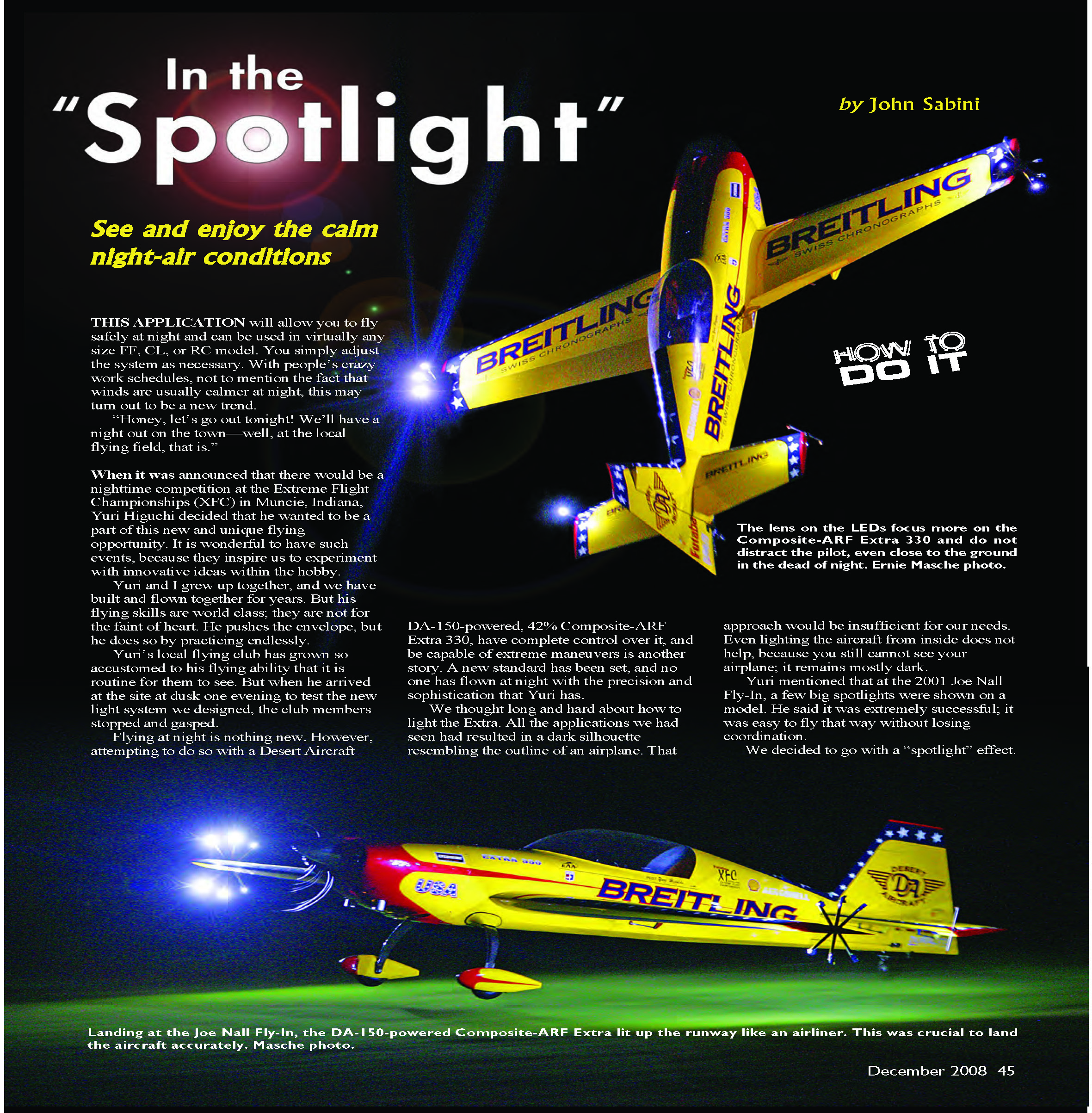
Flying at night is nothing new. However, attempting to do so with a Desert Aircraft DA-150-powered, 42% Composite-ARF Extra 330, have complete control over it, and be capable of extreme maneuvers is another story. A new standard has been set, and no one has flown at night with the precision and sophistication that Yuri has.
We thought long and hard about how to light the Extra. All the applications we had seen had resulted in a dark silhouette resembling the outline of an airplane. That approach would be insufficient for our needs. Even lighting the aircraft from inside does not help, because you still cannot see your airplane; it remains mostly dark.
Yuri mentioned that at the 2001 Joe Nall Fly-In, a few big spotlights were shown on a model. He said it was extremely successful; it was easy to fly that way without losing coordination. We decided to go with a "spotlight" effect.
That way, Yuri could see his model as clear as day, as opposed to seeing a silhouette of a dark aircraft, which can be easy to lose or hard to keep track of. This spotlight effect allows you to be in complete control of the airplane even when it's 1/2 mile away and perform extreme aerobatic maneuvers without losing orientation. It is amazing to think that such a simple concept has eluded us for so long.
At that point we needed a way to make it work, to be practical, and to be easy. I tackled this project for Yuri. It took me six months of research and testing, as well as brushing up on basic formulas and laws, to get things right. And with Yuri's flying ability, I knew he would be the one to give this venture the extra "wow" factor.
We realized that shining a light on an airplane was difficult. Mounting it close to the aircraft did not work. We needed to get distance from the airframe for the light to be sufficient. We chose to mount the lights on the wingtips and stabilizer tips so that the light would beam onto the flying surfaces and the fuselage.
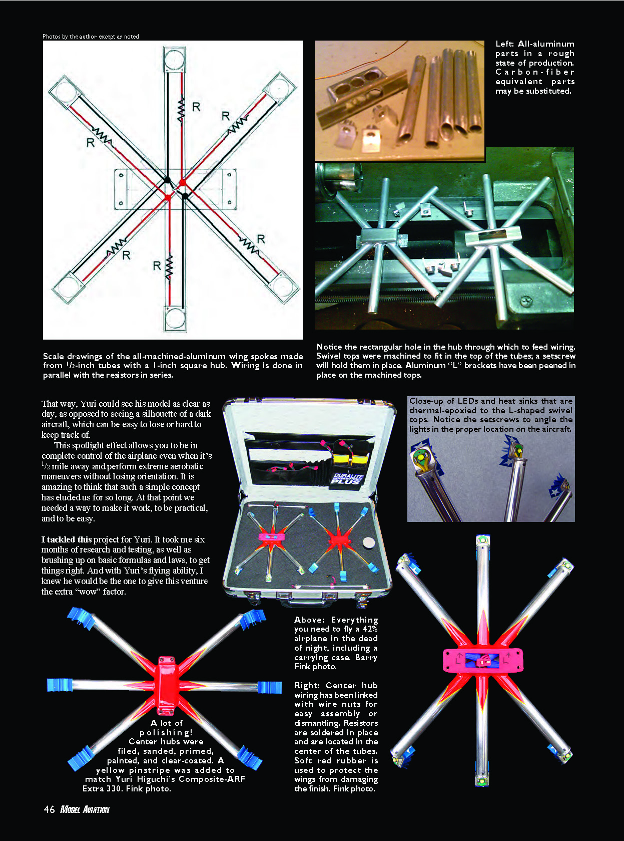
Yuri and I wanted a clean look, and the wiring needed to be simple. We came up with plug-in, removable light harnesses that were handmade from ultra-light aircraft-grade aluminum. Six 1/2-inch-diameter aluminum tubes are welded to a 1-inch square center hub and mounted to the ends of the wings. The stabilizers have two tubes. All this was constructed from raw materials, so a great deal of labor went into it. The hard part was engineering and designing it. Once we knew what to do, completing the harnesses took approximately 60 hours and plenty of polishing. I did not want them to look ugly—especially on Yuri's model. I constructed the "light fixtures," and Yuri handled the wiring and battery setup within the Extra. The added weight was nominal for a 42% aircraft. Each side of the model is independent of the other for redundancy.
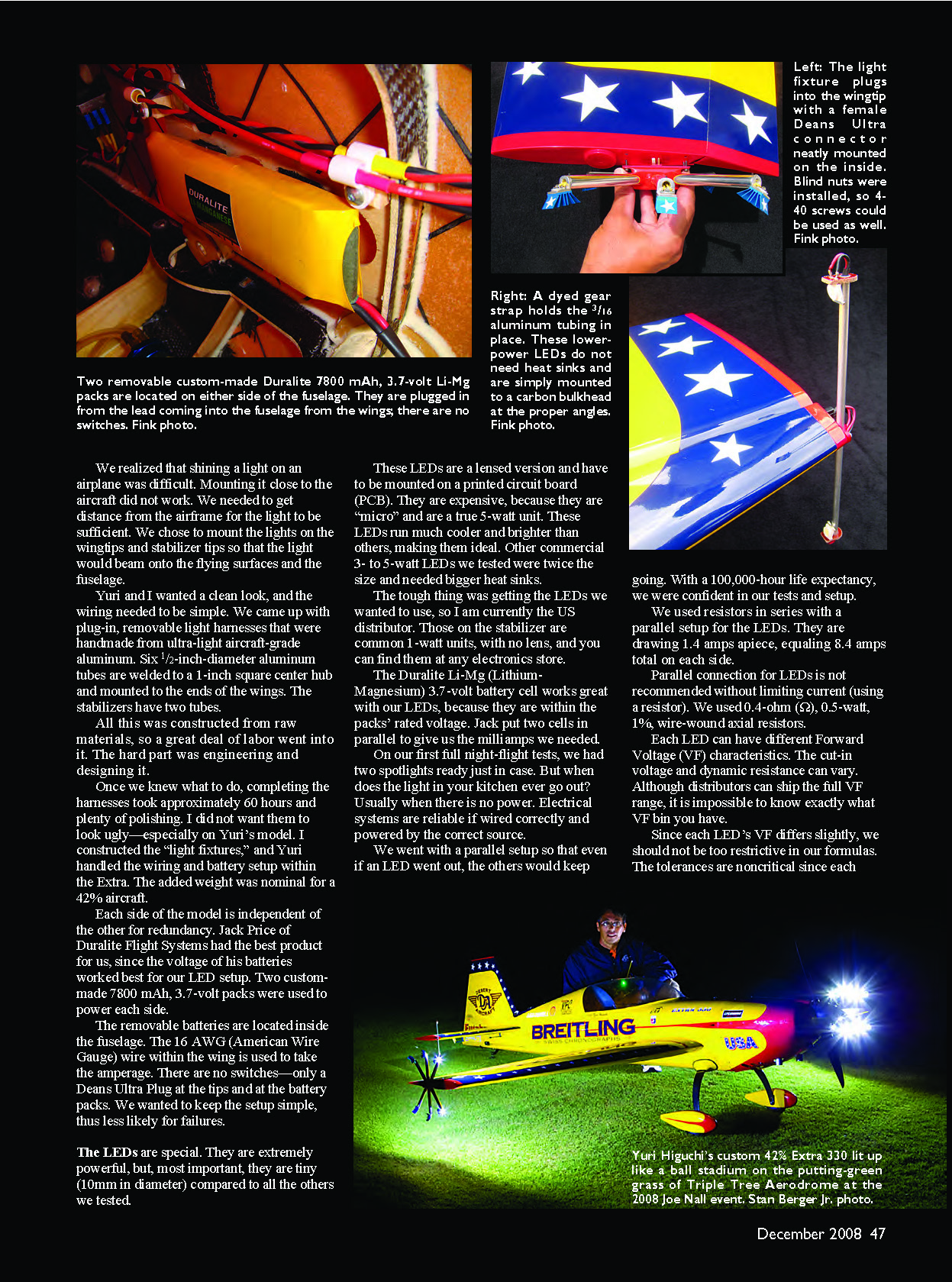
Jack Price of Duralite Flight Systems had the best product for us, since the voltage of his batteries worked best for our LED setup. Two custom-made 7800 mAh, 3.7-volt packs were used to power each side. The removable batteries are located inside the fuselage. The 16 AWG (American Wire Gauge) wire within the wing is used to take the amperage. There are no switches—only a Deans Ultra Plug at the tips and at the battery packs. We wanted to keep the setup simple, thus less likely for failures.
The LEDs are special. They are extremely powerful, but, most important, they are tiny (10 mm in diameter) compared to all the others we tested. These LEDs are a lensed version and have to be mounted on a printed circuit board (PCB). They are expensive, because they are "micro" and are a true 3-watt unit. These LEDs run much cooler and brighter than others, making them ideal. Other commercial 3- to 5-watt LEDs we tested were twice the size and needed bigger heat sinks.
The tough thing was getting the LEDs we wanted to use, so I am currently the US distributor. Those on the stabilizer are common 1-watt units, with no lens, and you can find them at any electronics store.
The Duralite Li-Mg (Lithium-Magnesium) 3.7-volt battery cell works great with our LEDs, because they are within the packs' rated voltage. Jack put two cells in parallel to give us the milliamps we needed.
On our first full night-flight tests, we had two spotlights ready just in case. But when does the light in your kitchen ever go out? Usually when there is no power. Electrical systems are reliable if wired correctly and powered by the correct source.
We went with a parallel setup so that even if an LED went out, the others would keep going. With a 100,000-hour life expectancy, we were confident in our tests and setup.
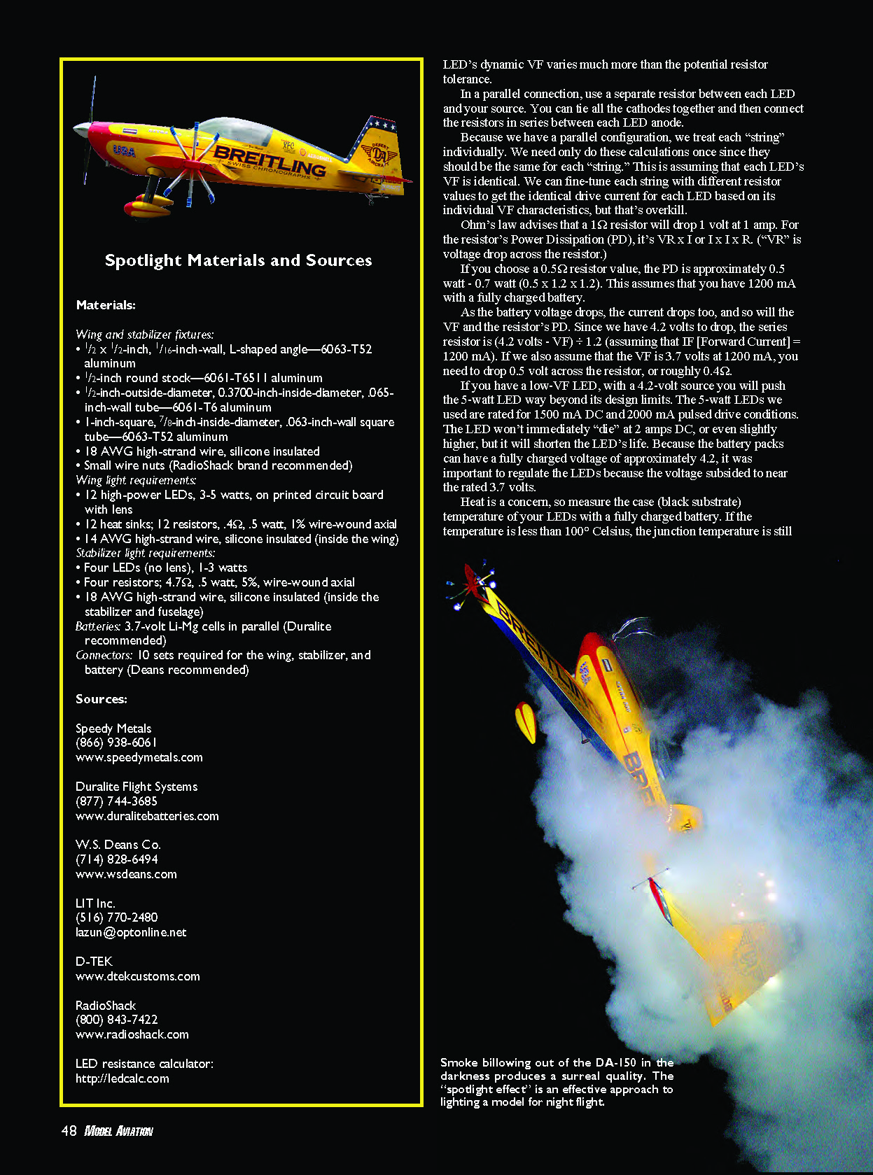
We used resistors in series with a parallel setup for the LEDs. They are drawing 1.4 amps apiece, equaling 8.4 amps total on each side.
Parallel connection for LEDs is not recommended without limiting current (using a resistor). We used 0.4-ohm, 0.5-watt, 1% wire-wound axial resistors.
Each LED can have different Forward Voltage (VF) characteristics. The cut-in voltage and dynamic resistance can vary. Although distributors can ship the full VF range, it is impossible to know exactly what VF bin you have.
Since each LED's VF differs slightly, we should not be too restrictive in our formulas. The tolerances are noncritical since each LED's dynamic VF varies much more than the potential resistor tolerance.
In a parallel connection, use a separate resistor between each LED and your source. You can tie all the cathodes together and then connect the resistors in series between each LED anode.
Because we have a parallel configuration, we treat each "string" individually. We need only do these calculations once since they should be the same for each "string." This is assuming that each LED's VF is identical. We can fine-tune each string with different resistor values to get the identical drive current for each LED based on its individual VF characteristics, but that's overkill.
Ohm's law advises that a 1-ohm resistor will drop 1 volt at 1 amp. For the resistor's Power Dissipation (PD), it's VR x I or I x I x R ("VR" is voltage drop across the resistor).
If you choose a 0.5-ohm resistor value, the PD is approximately 0.5 watt to 0.7 watt (0.5 x 1.2 x 1.2). This assumes that you have 1,200 mA with a fully charged battery.
As the battery voltage drops, the current drops too, and so will the VF and the resistor's PD. Since we have 4.2 volts to drop, the series resistor is (4.2 volts - VF) ÷ 1.2 (assuming that IF [Forward Current] = 1,200 mA). If we also assume that the VF is 3.7 volts at 1,200 mA, you need to drop 0.5 volt across the resistor, or roughly 0.4 ohm.
If you have a low-VF LED, with a 4.2-volt source you will push the 5-watt LED way beyond its design limits. The 5-watt LEDs we used are rated for 1,500 mA DC and 2,000 mA pulsed drive conditions. The LED won't immediately "die" at 2 amps DC, or even slightly higher, but it will shorten the LED's life. Because the battery packs can have a fully charged voltage of approximately 4.2, it was important to regulate the LEDs because the voltage subsided to near the rated 3.7 volts.
Heat is a concern, so measure the case (black substrate) temperature of your LEDs with a fully charged battery. If the temperature is less than 100° Celsius, the junction temperature is still safe (less than 150° Celsius). Cooler is always better and brighter.
A machined swivel aluminum top with a setscrew can adjust the angle of light as desired. We also angled the aluminum "L" brackets forward and back for the correct effect. We used LEDs with a lens to focus the light on the airframe.
A heat sink is needed to dissipate the generated heat, even in flight, because these special PCB-mounted 5-watt LEDs have to remain cool (125°–150° Celsius). The LEDs and heat sinks were glued in place to the swivel "L" bracket, with D-TEK's Arctic Silver Thermal Adhesive epoxy, to draw heat away from the LEDs to the heat sinks.
Yuri and I performed extensive ground- and flight-testing in daylight before we were confident to tackle the darkness of night; this was not a $50 foamie. The models that Yuri builds are works of art, and we were not about to take chances even though the light setup was reliable.
We wanted to have this project ready for the 2008 Joe Nall Fly-In in May. Yuri had accumulated roughly 20 night flights by the time we went.
We had fun with this, because we didn't tell anyone about it. We just went out at Joe Nall at nearly 10:30 in the evening, fired up the DA-150, and Yuri performed a takeoff with the Extra. It woke everyone in the tents and RVs and brought people back out to the flightline.
By the third day of the event, there were as many people on the flightline at 9:30 p.m. waiting to see Yuri fly as there were during the day. He did not disappoint. He was able to fly the airplane with the same level of precision as during the day.
On takeoff, Yuri immediately half-rolled the model. The area and ground were in complete darkness, and the wing lit up the grass as it went by. People were amazed by how visible the airplane was at more than one-half mile away.
Even high maneuvers such as the roller-coaster and flat spins were amazingly visible. 3-D maneuvers were as easy for Yuri in the daytime as they were at night. The high-alpha rollers were a few feet off the ground within the tree line. As the airplane went by the trees, their trunks were lit up!
The most amazing thing for most observers was to see the airplane rotate with the smoke on. That was one of the coolest things I had seen in awhile; it looked surreal. The lights illuminated the smoke that billowed out, creating an aura around the airplane. Wow!
Try installing spotlights on your model. Do some research and determine the type of lights you need for the aircraft you intend to use. Once you have the lighting picked out, select the power source. That will determine the necessary resistors and wiring.
Fly a model at night only after considering AMA's safety precautions, your ability as an RC pilot, and the airplane's suitability. This lighting system is the most brilliant I've seen in terms of offering the best ability to recognize the model while it's in flight, but it doesn't help the pilot recognize the terrain.
Night-flying isn't the activity in which to forget that we, as AMA members, represent a community that considers the reputation of aeromodeling a foremost priority. Have fun, but be responsible, sensible, and safe.
I am happy to have been a part of this project, but Yuri is the one who deserves the credit because of his flying capabilities. It took some ingenuity, teamwork, and determination, as well as the XFC, to inspire us to evolve the hobby into quite possibly a new era.
MA
John Sabini lazun@optonline.net
Transcribed from original scans by AI. Minor OCR errors may remain.

