
Grandson
By Ellis Grumer
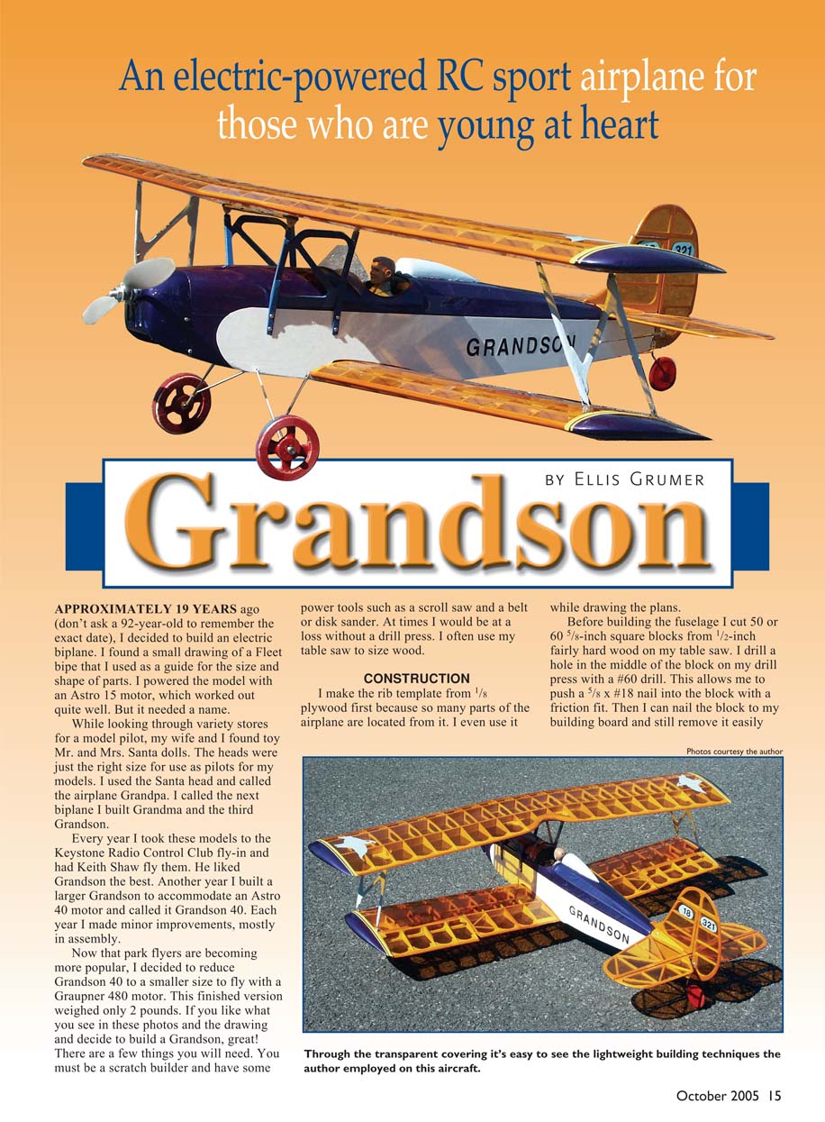
APPROXIMATELY 19 YEARS ago (don't ask a 92-year-old to remember the exact date), I decided to build an electric biplane. I found a small drawing of a Fleet biplane that I used as a guide for the size and shape of parts. I powered the model with an Astro 15 motor, which worked out quite well. But it needed a name.
While looking through variety stores for a model pilot, my wife and I found toy Mr. and Mrs. Santa dolls. The heads were just the right size for use as pilots for my models. I used the Santa head and called the airplane Grandpa. I called the next biplane I built Grandma and the third Grandson.
Every year I took these models to the Keystone Radio Control Club fly-in and had Keith Shaw fly them. He liked Grandson the best. Another year I built a larger Grandson to accommodate an Astro 40 motor and called it Grandson 40. Each year I made minor improvements, mostly in assembly.
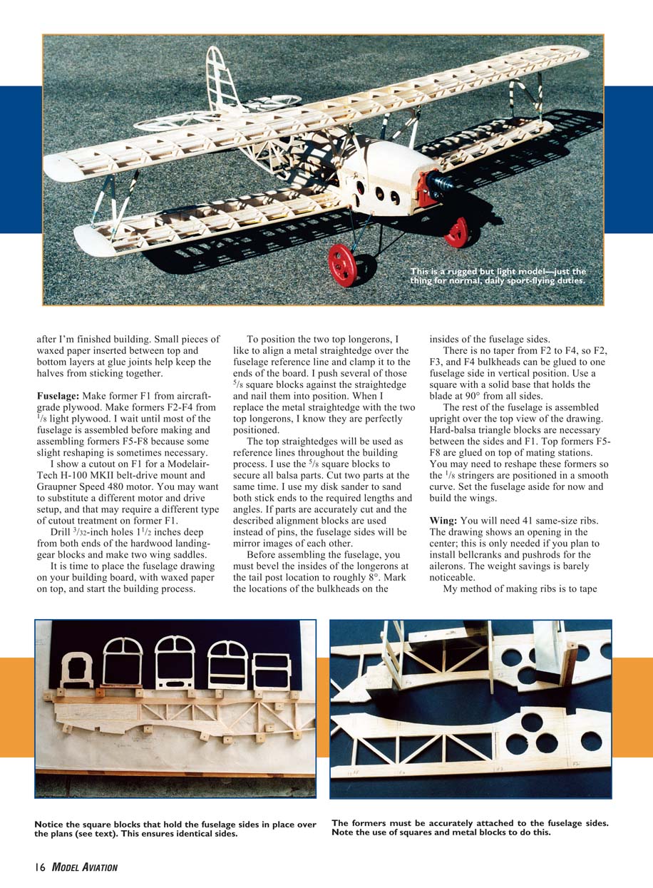
Now that park flyers are becoming more popular, I decided to reduce Grandson 40 to a smaller size to fly with a Graupner 480 motor. This finished version weighed only 2 pounds. If you like what you see in these photos and the drawings and decide to build a Grandson, great! There are a few things you will need. You must be a scratch builder and have some power tools such as a scroll saw and a belt or disk sander. At times I would be at a loss without a drill press. I often use my table saw to size wood.
CONSTRUCTION
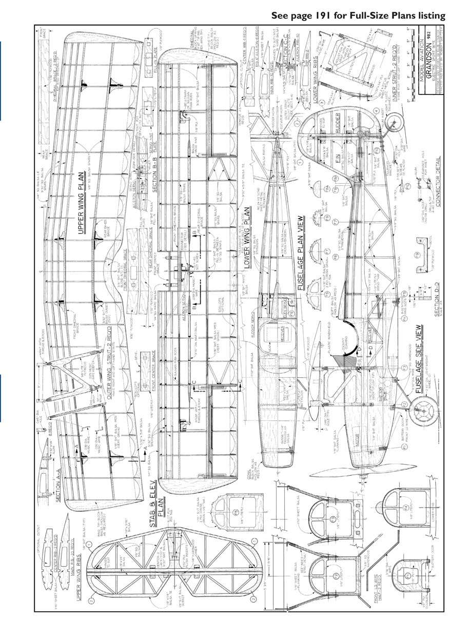
I make the rib template from 1/8 plywood first because so many parts of the airplane are located from it. I even use it while drawing the plans.
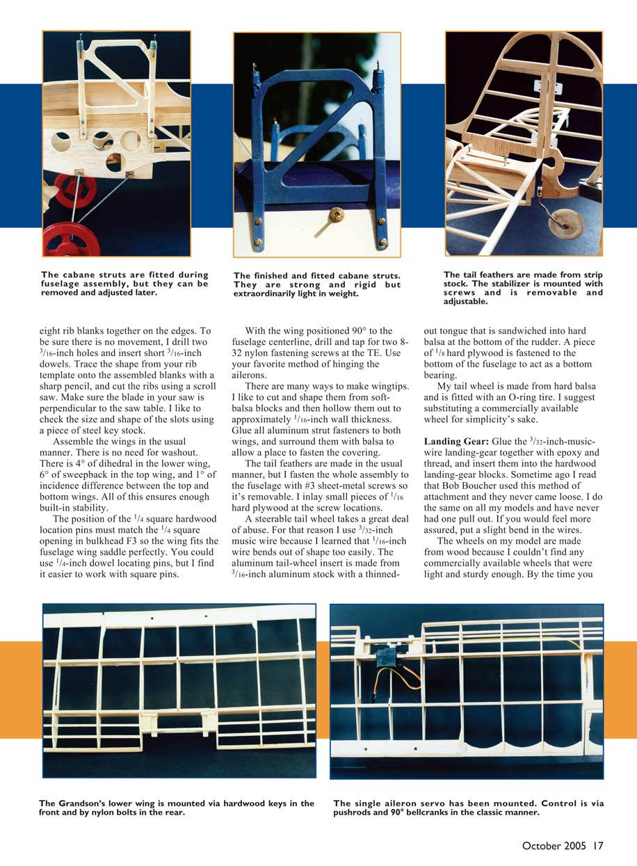
Before building the fuselage I cut 50 or 60 5/8-inch square blocks from 1/2-inch fairly hard wood on my table saw. I drill a hole in the middle of the block on my drill press with a #60 drill. This allows me to push a 5/8 x #18 nail into the block with friction fit. Then I can nail the block to my building board and still remove it easily.
Small pieces of waxed paper inserted between top and bottom layers at glue joints help keep the halves from sticking together.
Fuselage
Make former F1 from aircraft-grade plywood. Make formers F2–F4 from 1/8 light plywood. I wait until most of the fuselage is assembled before making and assembling formers F5–F8 because some slight reshaping is sometimes necessary.
I show a cutout on F1 for a Modelair-Tech H-100 MKII belt-drive mount and Graupner Speed 480 motor. You may want to substitute a different motor and drive setup, and that may require a different type of cutout treatment on former F1.
Drill 3/32-inch holes 1 1/2 inches deep from both ends of the hardwood landing-gear blocks and make two wing saddles.
It is time to place the fuselage drawing on your building board, with waxed paper on top, and start the building process.
To position the two top longerons, I like to align a metal straightedge over the fuselage reference line and clamp it to the ends of the board. I push several of those 5/8 square blocks against the straightedge and nail them into position. When I replace the metal straightedge with the two top longerons, I know they are perfectly positioned.
The top straightedges will be used as reference lines throughout the building process. I use the 5/8 square blocks to secure all balsa parts. Cut two parts at the same time. I use my disk sander to sand both sticks into the required lengths and angles. If parts are accurately cut and the described alignment blocks are used instead of pins, the fuselage sides will be mirror images of each other.
Before assembling the fuselage, you must bevel the insides of the longerons at the tail post location to roughly 8°. Mark the locations of the bulkheads on the insides of the fuselage sides.
There is no taper from F2 to F4, so F2, F3, and F4 bulkheads can be glued to one fuselage side in vertical position. Use a square with a solid base that holds the blade at 90° from all sides.
The rest of the fuselage is assembled upright over the top view of the drawing. Hard-balsa triangle blocks are necessary between the sides and F1. Top formers F5–F8 are glued on to mating stations. You may need to reshape these formers so the 1/8 stringers are positioned in a smooth curve. Set the fuselage aside for now and build the wings.
Wing
You will need 41 same-size ribs. The drawing shows an opening in the center; this is only needed if you plan to install bellcranks and pushrods for the ailerons. The weight savings is barely noticeable.
My method of making ribs is to tape eight rib blanks together on the edges. To be sure there is no movement, I drill two 3/16-inch holes and insert short 3/16-inch dowels. Trace the shape from your rib template onto the assembled blanks with a sharp pencil, and cut the ribs using a scroll saw. Make sure the blade in your saw is perpendicular to the saw table. I like to check the size and shape of the slots using a piece of steel key stock.
Assemble the wings in the usual manner. There is no need for washout. There is 4° of dihedral in the lower wing, 6° of sweepback in the top wing, and 1° of incidence difference between the top and bottom wings. All of this ensures enough built-in stability.
The position of the 1/4 square hardwood location pins must match the 1/4 square opening in bulkhead F3 so the wing fits the fuselage wing saddle perfectly. You could use 1/4-inch dowel locating pins, but I find it easier to work with square pins.
With the wing positioned 90° to the fuselage centerline, drill and tap for two 8-32 nylon fastening screws at the TE. Use your favorite method of hinging the ailerons.
There are many ways to make wingtips. I like to cut and shape them from soft-balsa blocks and then hollow them out to approximately 1/16-inch wall thickness. Glue all aluminum strut fasteners to both wings, and surround them with balsa to allow a place to fasten the covering.
Tail feathers
The tail feathers are made in the usual manner, but I fasten the whole assembly to the fuselage with #3 sheet-metal screws so it's removable. I inlay small pieces of 1/16 hard plywood at the screw locations.
A steerable tail wheel takes a great deal of abuse. For that reason I use 3/32-inch music wire because I learned that 1/16-inch wire bends out of shape too easily. The aluminum tail-wheel insert is made from 3/16-inch aluminum stock with a thinned-out tongue that is sandwiched into hard balsa at the bottom of the rudder. A piece of 1/8 hard plywood is fastened to the bottom of the fuselage to act as a bottom bearing.
My tail wheel is made from hard balsa and is fitted with an O-ring tire. I suggest substituting a commercially available wheel for simplicity's sake.
Landing Gear
Glue the 3/32-inch-music-wire landing-gear together with epoxy and thread, and insert them into the hardwood landing-gear blocks. Sometime ago I read that Bob Boucher used this method of attachment and they never came loose. I do the same on all my models and have never had one pull out. If you would feel more assured, put a slight bend in the wires.
The wheels on my model are made from wood because I couldn't find any commercially available wheels that were light and sturdy enough. By the time you read this, you may be able to purchase good-looking, light, durable wheels. On this model I moved the gear forward 1/2 inch to prevent nose-over on landing.
Inner Struts
The inner wing struts (also known as cabane struts) usually consist of front and back legs as separate pieces with angle braces between them. I have always found it difficult to work with separate pieces. Section AA shows front and back legs and angle braces as a single unit.
Tape two pieces of 1/8 x 3 1/4 x 3 1/4-inch light plywood together and cut on your scroll saw. Epoxy 1/64 x 1/4-inch aluminum strips to the inside of the legs for strength. There are also 20° hardwood angle braces where the legs attach to the fuselage. Work closely with all dimensions and angles because these struts hold the top wing in a precise location. When you glue the .039-inch-music-wire fasteners to the leg tops, you will be setting the 2° positive incidence of the top wing.
Outboard Struts
Assemble the upper and lower wings to the fuselage, and position this assembly on your building board with the tops of the longerons parallel to the board. Start with an incidence-meter reading on the wing. It should read 3° higher than the reading on the bottom wing. If there are no warps in the wing, you should get the same readings at the tips.
Find some way to hold the tips firmly in position so they do not move while you work on the struts. The bottom wing can be weighed down over blocks. The top wing can be held in position with upright strips of wood that are C-clamped to a rib of the bottom wing and to a rib of the top wing.
The outboard struts are made basically the same as the inboard struts, from 1/8" light plywood. Since some minor errors could have crept in by now, you may prefer to make a cardboard template of the outboard-strut drawing and correct any errors. The two bends at the top of the struts and the spring-wire-formed keepers at the bottoms are working out well on my models.
Final Assembly
It is time to get back to fuselage work. It is also the best time to install the power-train components. Weight distribution is necessary to obtain the correct CG. Adding extra weight to achieve proper balance on an electric model is a no-no! This is especially true on an airplane that is using a BEC because there is no separate battery that can be moved fore or aft for CG adjustment.
My first Grandson model was tailheavy. I had to reposition the motor 1/2 inch farther forward on the mount to compensate. On this model I made the nose 1/2 inch longer and relocated the rudder and elevator servos roughly 3 inches farther forward.
This model was obviously designed to use the electric components that were available at the time it was built. Electric-modeling technology is advancing rapidly; there will be more powerful, lighter, and more efficient components and systems available by the time you read this. There is plenty of room in the fuselage to accommodate these new systems, and some creative thinking will allow you to use them to your advantage.
A good modern power system would be a small brushless motor driven by a small three-cell Li-Poly battery. That should provide plenty of power. Since Li-Poly batteries are much lighter than NiCds, fasten the Li-Poly pack to the inside of the battery door that is shown on the plans.
When you are finished working inside, it is time to finish the top of the fuselage. I planked the cowl from F1 to F2. I started with 1/8"-thick planks on top of the longerons and gradually increased the thickness of the planks to 1/4" on the top where there is more curvature. Use 1/16" balsa sheet from F2 to F4. This will end up being approximately 1/32"-inch thick when sanded. The nose cap is made from built-up 1/4" balsa and held in place with two #2 sheet-metal screws.
Finishing
I use lightweight Solarfilm or Coverite Black Baron Film for covering. I select transparent film for large areas such as the wings because I feel that it is lighter in weight than solid film.
Flying
The new park flyer plastic propellers with thin blades should give more thrust with less resistance than wood propellers. They also weigh less.
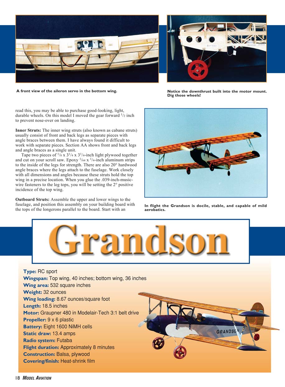
The eight-cell, 1600 mAh NiMH battery may not give as much thrust as a good, plain Ni-Cd battery, but I can make the model take off from closely cut grass in roughly 75 feet and fly usual lazy eights for five to eight minutes. Expert fliers can put in a few aerobatics.
At our Lehigh Valley RC Society electric meet I was fortunate to have Bob Kopski, Tom Hunt, and Bob Hunt fly my Grandson. I received a variety of comments and suggestions. Tom and Bob Kopski favored the Ni-Cd cells, such as Sanyo CP1300 SCRs; I will try these. Bob Hunt said we should put the design in MA as a builder's project, and here it is! MA
Ellis Grumer 321 Aurora St. Phillipsburg NJ 08865
Transcribed from original scans by AI. Minor OCR errors may remain.

