
Gee Bee Model Z
A different look for C:
ROUGHLY THREE YEARS ago at a local hobby shop, I picked up a copy of Model Aviation in pursuit of some Control Line (CL) information. That, coupled with a recent visit with my younger brother, brought back the fun and exciting memories of flying.
When we were young, after farm chores we would drag out our 1/2A Goldberg models. My brother’s was painted all yellow, and mine was painted orange and black—school colors.
Combat was our favorite game, and we would fly until one of us couldn’t fly anymore; that is, until one of the airplanes was lacking too many pieces and enough covering to keep flying!
Now that I have a wife and two boys, I thought this would be a great father-and-son activity, and my wife would be entertained in the process. So after many years of no airplanes, we’re back at it. (For the last four years, we’ve enjoyed going to area CL contests and camping and cooking out.)
The Granville Brothers’ aircraft, commonly called Gee Bees, have always been “awesome” to me. After finding an article about Pat Johnston’s Profile Scale R-2 Gee Bee in the May 1996 Model Aviation, I knew I’d found my beginner Stunter.
A call to Pat to help me reduce his .46-powered model to a .35-.40 size gave me an airplane that would fit in my car trunk. Thanks to Pat for his help and information.
During competition with the R-2, many individuals came up to talk to me about the Gee Bees and their builders, the Granville Brothers.
A trip to the local library brought me up to speed on the five brothers’ lives, which were filled with hard work and fueled by their dreams for success and fame. Racing became their passion and livelihood.
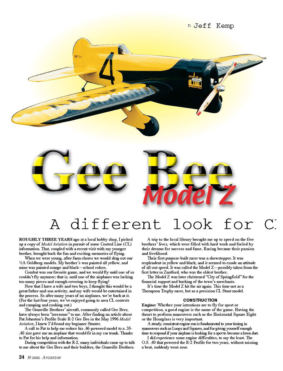
Their first purpose-built racer was a showstopper. It was resplendent in yellow and black, and it seemed to exude an attitude of all-out speed. It was called the Model Z—possibly taken from the first letter in Zantford, who was the oldest brother.
The Model Z was later christened “City of Springfield” for the financial support and backing of the town’s merchants.
It’s time the Model Z hit the air again. This time not as a Thompson Trophy racer, but as a precision CL stunt model.
CONSTRUCTION
Engine:
Whether your intentions are to fly for sport or competition, a good engine is the name of the game. Having the thrust to perform maneuvers such as the Horizontal Square Eight or the Hourglass is very important.
A steady, consistent engine run is fundamental to your timing in maneuvers such as Loops and Squares, and for giving yourself enough time to respond if your airplane is looking for a spot to become a lawn dart.
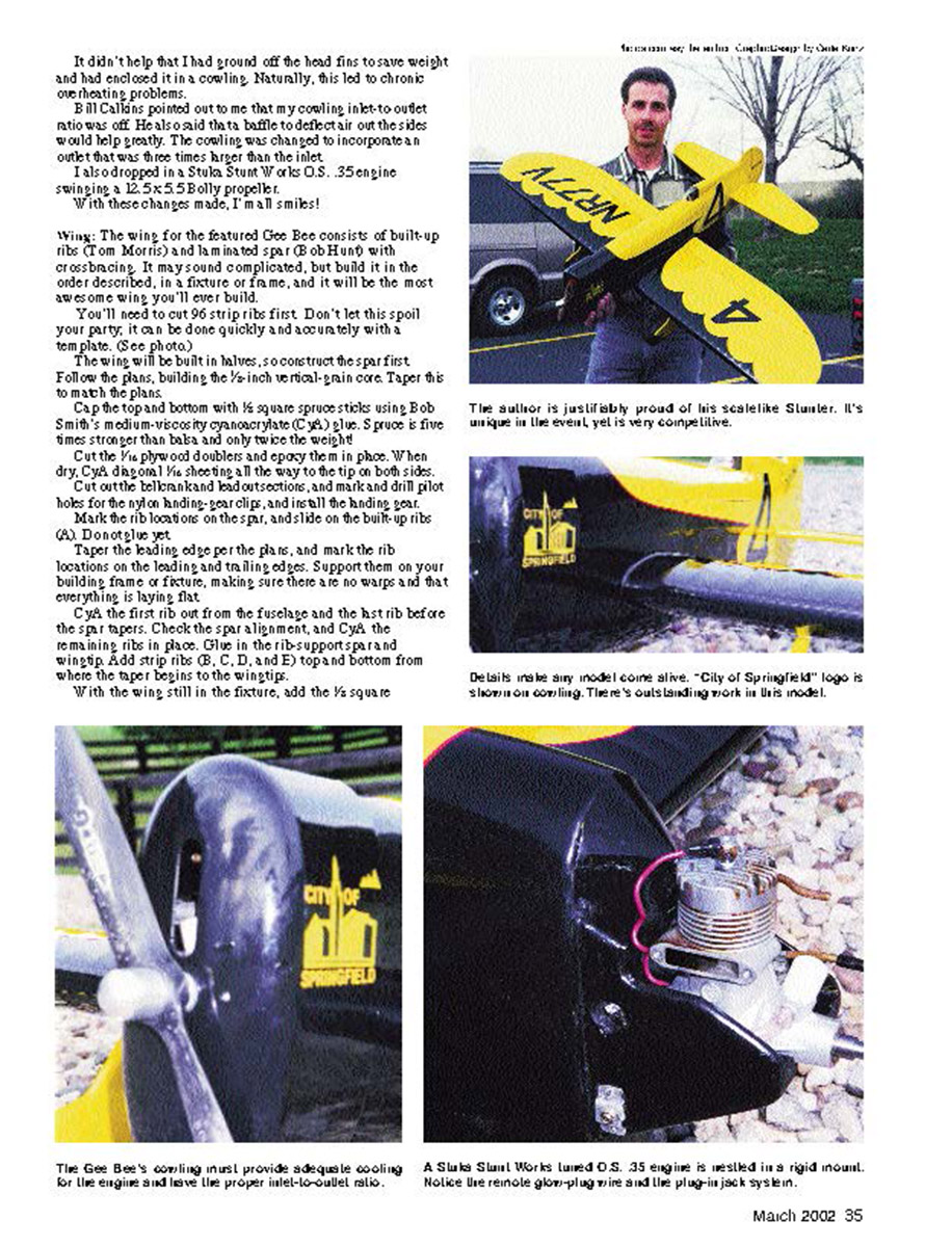
I did experience engine difficulties, to say the least. The O.S. .40 that powered the R-2 Profile for two years, without missing a beat, suddenly went sour. It didn't help that I had ground off the head fins to save weight and had enclosed it in a cowling. Naturally, this led to chronic overheating problems.
Bill Calkins pointed out to me that my cowling inlet-to-outlet ratio was off. He also said that a baffle to deflect air out the sides would help greatly. The cowling was changed to incorporate an outlet that was three times larger than the inlet.
I also dropped in a Stuka Stunt Works O.S. .35 engine swinging a 12.5x5.5 Bolly propeller.
With these changes made, I'm all smiles!
Wings:
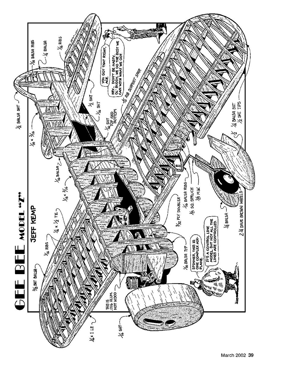
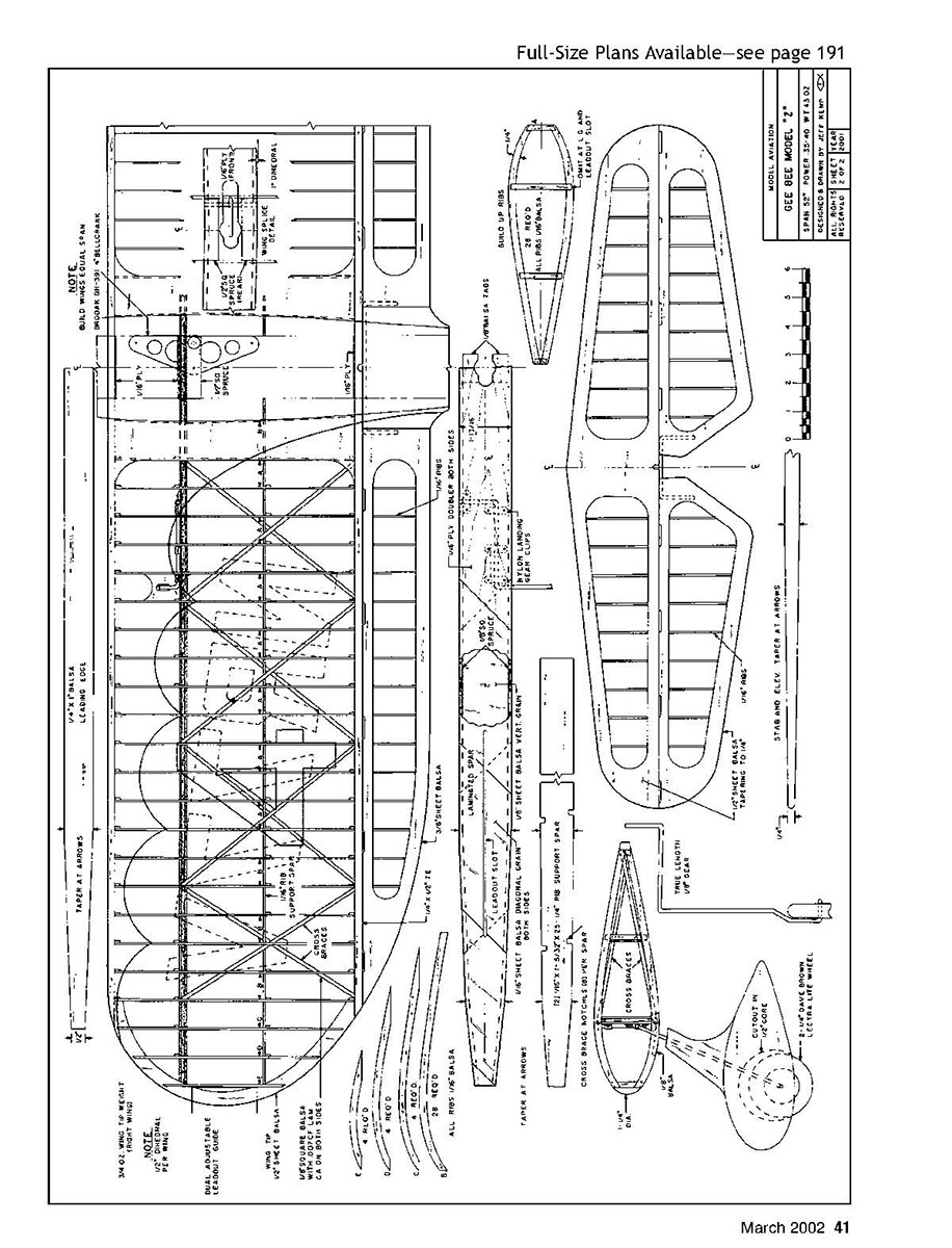
The wing for the featured Gee Bee consists of built-up ribs (Tom Morris) and laminated spar (Bob Hunt) with crossbracing. It may sound complicated, but build it in the order described, in a fixture or frame, and it will be the most awesome wing you'll ever build.
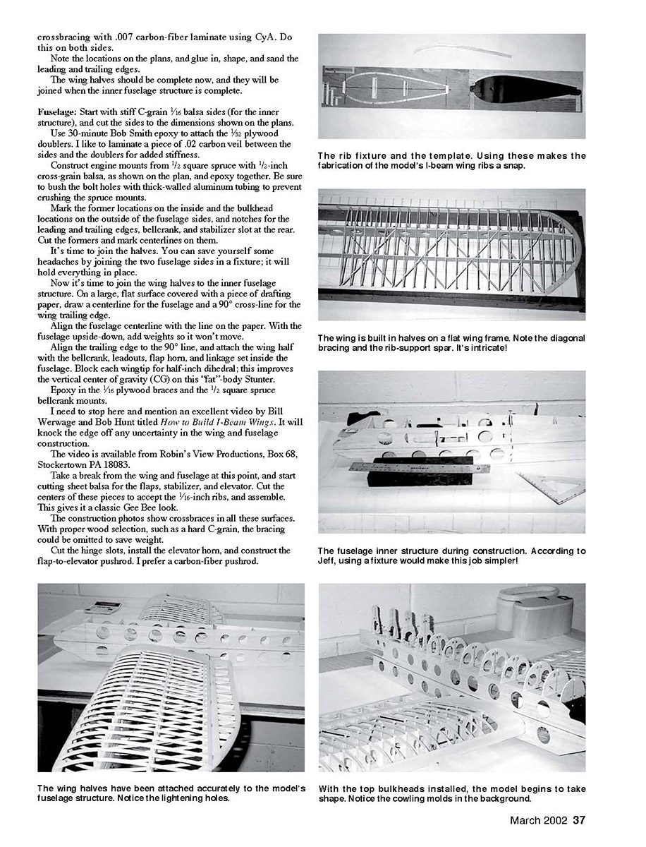
You'll need to cut 96 strip ribs first. Don't let this spoil your party, it can be done quickly and accurately with a template. (See photo)
The wing will be built in halves, so construct the spars first. Follow the plans, building the 1/8-inch vertical-grain core. Taper this to match the plans.
Cap the top and bottom with 1/8 square spruce sticks using Bob Smith's medium-viscosity cyanoacrylate (CYA) glue. Spruce is five times stronger than balsa and only twice the weight!
Cut the 1/8 plywood doublers and epoxy them in place. When dry, CYA diagonal 1/16 sheeting all the way to the tip on both sides.
Cut out the bellcrank leadout sections, and mark and drill pilot holes for the nylon landing-gear clips, and install the landing gear.
Mark the rib locations on the spar, and slide on the built-up ribs (A). Do not glue yet.
Taper the leading edge per the plans, and mark the rib locations on the leading and trailing edges. Support them on your building frame or fixture, making sure there are no warps and that everything is laying flat.
CYA the first rib out from the fuselage and the last rib before the spars tapers. Check the spar alignment, and CYA the remaining ribs in place. Glue in the rib-supports and wingtip. Add strip ribs (B, C, D and E) top and bottom from where the taper begins to the wingtip.
With the wing still in the fixture, add the 1/8 square crossbracing with .007 carbon-fiber laminate using CyA. Do this on both sides.
Note the locations on the plans, and glue in, shape, and sand the leading and trailing edges.
The wing halves should be complete now, and they will be joined when the inner fuselage structure is complete.
Fuselage:
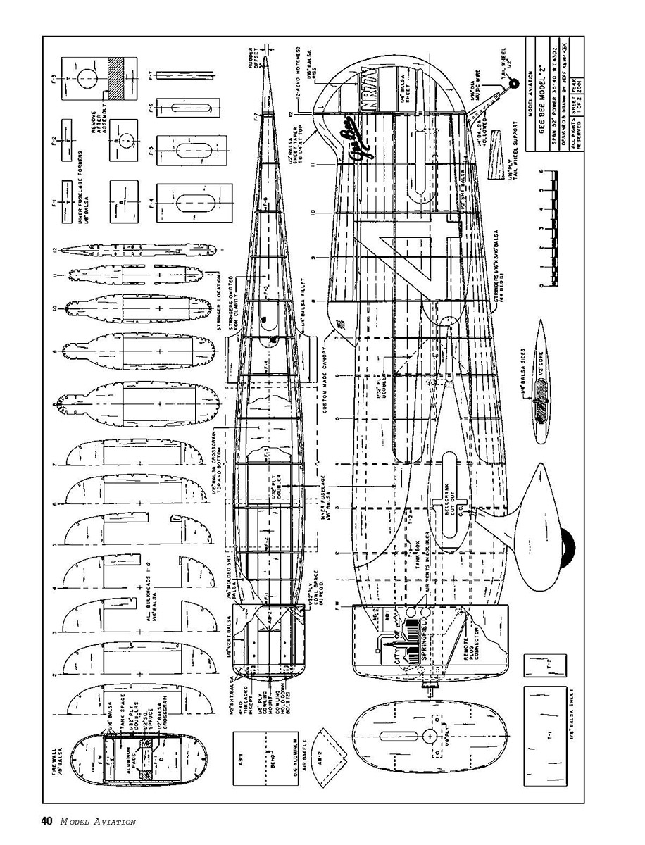
Start with stiff C-grain 1/16 balsa sides (for the inner structure), and cut the sides to the dimensions shown on the plans. Use 30-minute Bob Smith epoxy to attach the 1/8 plywood doublers. I like to laminate a piece of .02 carbon veil between the sides and the doublers for added stiffness.
Construct engine mounts from 1/2 square spruce with 1/2-inch cross-grain balsa, as shown on the plan, and epoxy together. Be sure to bush the bolt holes with thick-walled aluminum tubing to prevent crushing the spruce mounts.
Mark the former locations on the inside and the bulkhead locations on the outside of the fuselage sides, and notches for the leading and trailing edges, bellcrank, and stabilizer slot at the rear. Cut the formers and mark centerlines on them.
It's time to join the halves. You can save yourself some headaches by joining the two fuselage sides in a fixture; it will hold everything in place.
Now it's time to join the wing halves to the inner fuselage structure. On a large, flat surface covered with a piece of drafting paper, draw a centerline for the fuselage and a 90° cross-line for the wing trailing edge.
Align the fuselage centerline with the line on the paper. With the fuselage upside-down, add weights so it won't move.
Align the trailing edge to the 90° line, and attach the wing half with the bellcrank, leadouts, flap horn, and linkage set inside the fuselage. Block each wingtip for half-inch dihedral; this improves the vertical center of gravity (CG) on this "fat"-body Stunter.
Epoxy in the 1/16 plywood braces and the 1/2 square spruce bellcrank mounts.
I need to stop here and mention an excellent video by Bill Werwage and Bob Hunt titled How to Build I-Beam Wings. It will knock the edge off any uncertainty in the wing and fuselage construction.
The video is available from Robin's View Productions, Box 68, Stockertown PA 18083.
Take a break from the wing and fuselage at this point, and start cutting sheet balsa for the flaps, stabilizer, and elevator. Cut the centers of these pieces to accept the 1/16-inch ribs, and assemble. This gives it a classic Gee Bee look.
The construction photos show crossbraces in all these surfaces. With proper wood selection, such as a hard C-grain, the bracing could be omitted to save weight.
Cut the hinge slots, install the elevator horn, and construct the flap-to-elevator pushrod. I prefer a carbon-fiber pushrod.
At this point you can attach the horizontal stabilizer to the fuselage. Fasten all linkages in permanently.
It's time to box in the fuselage for strength. Use 1/16 balsa cross-grain sheeting top and bottom.
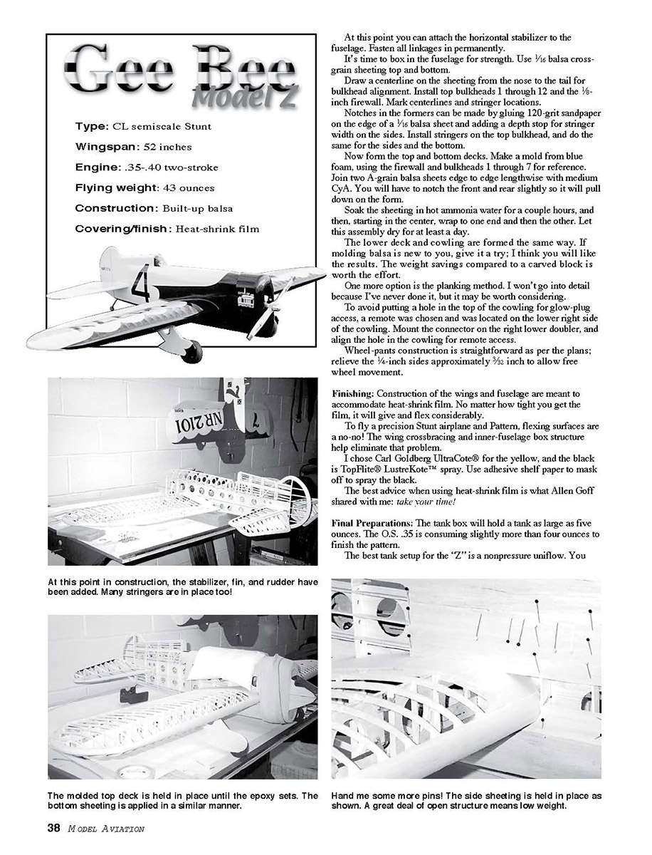
Draw a centerline on the sheeting from the nose to the tail for bulkhead alignment. Install top bulkheads 1 through 12 and the 1/8-inch firewall. Mark centerlines and stringer locations.
Notches in the formers can be made by gluing 120-grit sandpaper on the edge of a 1/16 balsa sheet and adding a depth stop for stringer width on the sides. Install stringers on the top bulkhead, and do the same for the sides and the bottom.
Now form the top and bottom decks. Make a mold from blue foam, using the firewall and bulkheads 1 through 7 for reference. Join two A-grain balsa sheets edge to edge lengthwise with medium CyA. You will have to notch the front and rear slightly so it will pull down on the form.
Soak the sheeting in hot ammonia water for a couple hours, and then, starting in the center, wrap to one end and then the other. Let this assembly dry for at least a day.
The lower deck and cowling are formed the same way. If molding balsa is new to you, give it a try; I think you will like the results. The weight savings compared to a carved block is worth the effort.
One more option is the planking method. I won't go into detail because I've never done it, but it may be worth considering.
To avoid putting a hole in the top of the cowling for glow-plug access, a remote was chosen and was located on the lower right side of the cowling. Mount the connector on the right lower doubler, and align the hole in the cowling for remote access.
Wheel-pants construction is straightforward as per the plans; relieve the 1/4-inch sides approximately 3/32 inch to allow free wheel movement.
Finishing:
Construction of the wings and fuselage are meant to accommodate heat-shrink film. No matter how tight you get the film, it will give and flex considerably.
To fly a precision Stunt airplane and Pattern, flexing surfaces are a no-no! The wing crossbracing and inner-fuselage box structure help eliminate that problem.
I chose Carl Goldberg UltraCote® for the yellow, and the black is TopFlite® LustreKote™ spray. Use adhesive shelf paper to mask off to spray the black.
The best advice when using heat-shrink film is what Allen Goff shared with me: take your time!
Final Preparations:
The tank box will hold a tank as large as five ounces. The O.S. .35 is consuming slightly more than four ounces to finish the pattern.
The best tank setup for the "Z" is a nonpressure uniflow. You will need to extend the overflow tube to the front of the engine, protruding slightly from the cowling intake.
You will also need to relocate the overflow on the tank. Close off the bottom and relocate it at the upper corner, and extend the tubing through a hole in the front cowling and plug it off after fueling.
The balance point is shown on the plans. It finished ready to fly in the CG department—I couldn't do that again if I tried.
However, it is a little slightly tail-heavy; add some weight to the nose; a short, stubby airplane does not need to be tail-heavy!
I use 63 feet of .012-inch-diameter solid line and shoot for 5.1 to 5.2 seconds per lap.
Before you start construction, set a goal for your aircraft's finished weight. If stunt contesting is in your plans, think light all over. Use only four- to six-pound-per-cubic-foot balsa, and use lightening holes in the structure.
The plans don't show the cutouts to save weight, but the photos should prove helpful in this respect.
If you would like to save time and effort, you can order the molded deck, canopy, and extended tongue muffler; just contact me.
This project is the result of many great, skilled modelers' efforts. A big thank you to the Capital City Control Liners. The members of this fine club were my on-the-spot troubleshooters, great minds flocked together.
I showed up at the AMA Nationals with the first outline of the Gee Bee Z on paper, and the following fine individuals helped sort out my mistakes and offered some much-needed advice. Thanks to Bob Hunt, Ted Fancher, Windy Utromowski, John and Jack Sundetland, Bob McDonald, Jim Lee, and Joe Reinhart.
And thanks, especially, to Sharon for the coffee and encouragement.
Go build this air-racer classic, and enjoy the thrill of watching the yellow-and-black City of Springfield fill the sky!
— Ed Miller
Transcribed from original scans by AI. Minor OCR errors may remain.

