
FrankenFoamy
Michael S. Blott
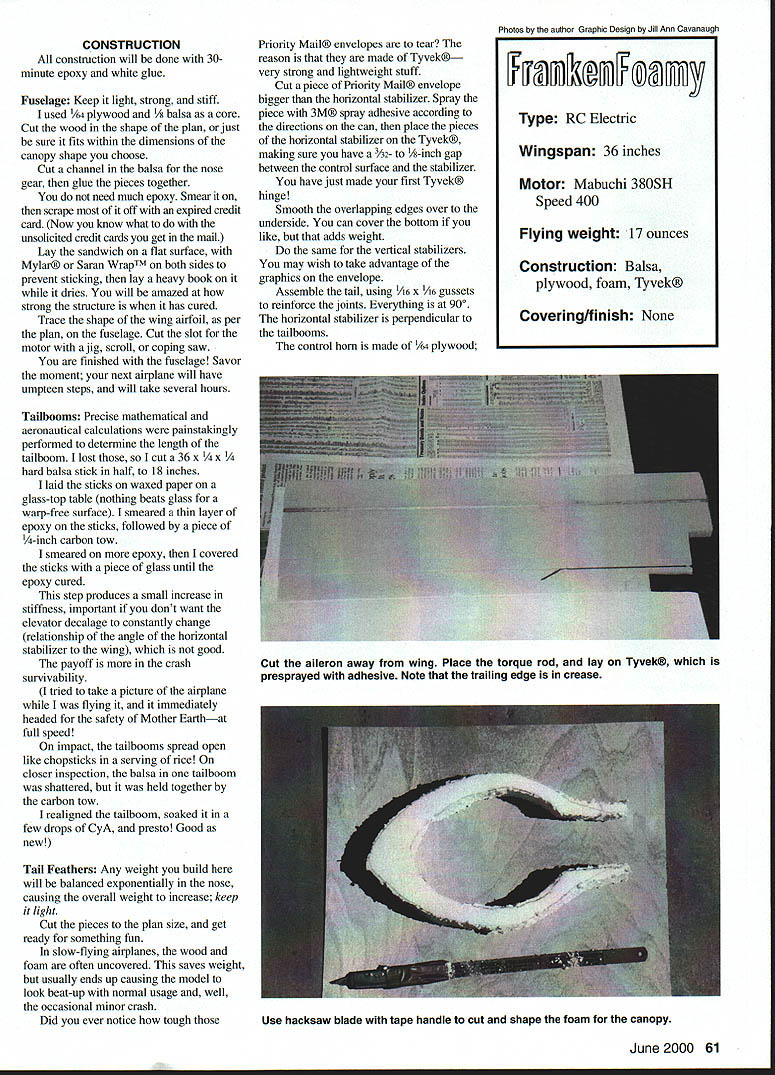
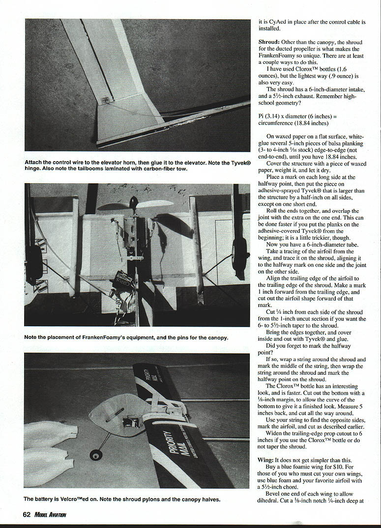
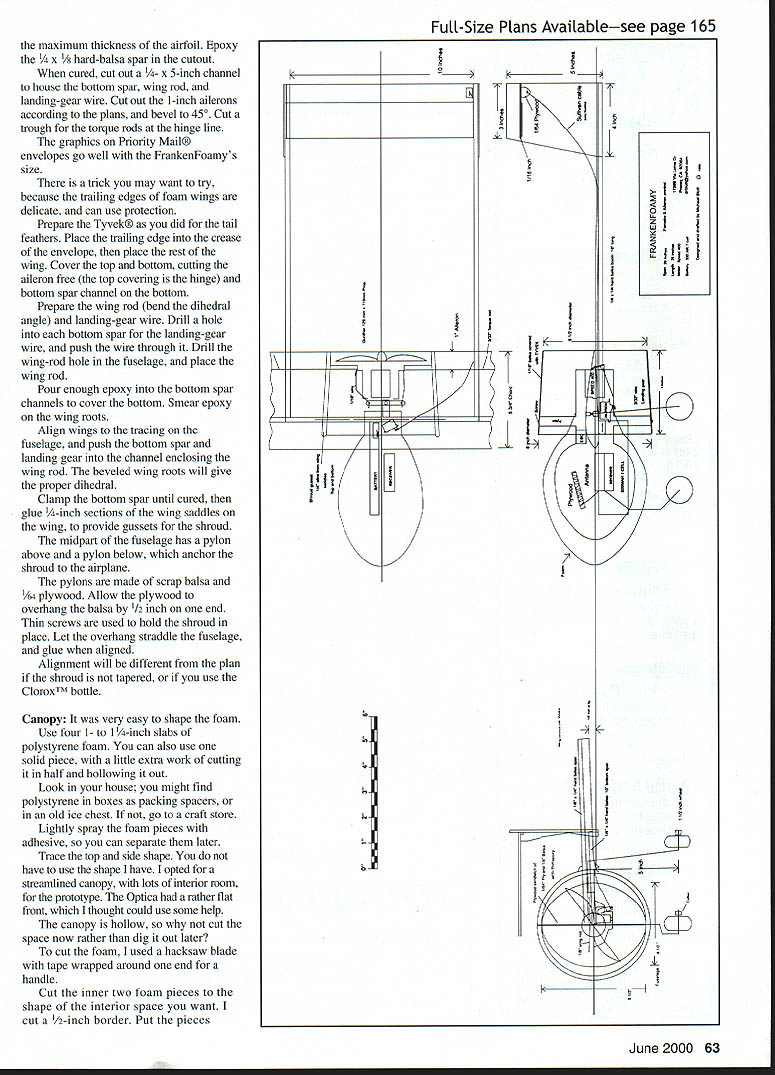
Several years ago I rented a largely forgettable movie—Slipstream. The memorable part was an unusual aircraft that I later learned was the Edgley Optica; it looked like a turbine fan trying to swallow a helicopter!
The thought running through my mind was, "How do I make a model of this?"
I had been mostly a glider pilot up to that point and was getting into electric flight. The Edgley fuselage consisted mainly of the "helicopter" canopy, so where would the stuff (radio, servos, batteries, etc.) go? My first thought was the wing. I proceeded to scale the airplane to do this, when the plans presented here popped into my head.
The airplane would have to have landing gear, because the shroud would be destroyed in belly landings. How would I build a clear canopy strong enough to mount nose gear?
I was trying to make the model as scale as possible, when I should have been thinking in more practical terms. The profile fuselage covered in foam was the answer; simplicity and strength would make this building project easy.
I had some blue foam wing cores from an unbuilt blue-foamie. The blue-foamie flew, and my airplane should fly if I used the same wings, motor, and weight—right?
Construction
All construction will be done with 30-minute epoxy and white glue.
Fuselage
Keep it light, strong, and stiff. I used 1/4-inch plywood and 1/8-inch balsa as a core. Cut the wood in the shape of the plan, or just be sure it fits within the dimensions of the canopy shape you choose.
Cut a channel in the balsa for the nose gear, then glue the pieces together. You do not need much epoxy. Smear it on, then scrape most of it off with an expired credit card.
Lay the sandwich on a flat surface, with Mylar® or Saran Wrap™ on both sides to prevent sticking, then lay a heavy book on it while it dries. You will be amazed at how strong the structure is when it has cured.
Trace the shape of the wing airfoil, as per the plan, on the fuselage. Cut the slot for the motor with a jig, scroll, or coping saw.
You are finished with the fuselage! Savor the moment; your next airplane will have umpteen steps and will take several hours.
Tailbooms
Precise mathematical and aeronautical calculations were painstakingly performed to determine the length of the tailboom. I lost those, so I cut a 36 x 1/4 x 1/4-inch hard balsa stick in half, to 18 inches.
I laid the sticks on waxed paper on a glass-top table (nothing beats glass for a warp-free surface). I smeared a thin layer of epoxy on the sticks, followed by a piece of 1/4-inch carbon tow. I smeared on more epoxy, then I covered the sticks with a piece of glass until the epoxy cured.
This step produces a small increase in stiffness, important if you don't want the elevator decalage (relationship of the angle of the horizontal stabilizer to the wing) to constantly change, which is not good. The payoff is more in crash survivability.
On impact, the tailbooms spread open like chopsticks in a serving of rice! On closer inspection, the balsa in one tailboom was shattered, but it was held together by the carbon tow. I realigned the tailboom, soaked it in a few drops of CA, and presto—good as new!
Tail feathers
Any weight you build here will be balanced exponentially in the nose, causing the overall weight to increase; keep it light. Cut the pieces to plan size, and get ready for something fun.
In slow-flying airplanes, the wood and foam are often uncovered. This saves weight, but usually ends up causing the model to look beat-up with normal usage and the occasional minor crash.
Did you ever notice how tough those Priority Mail® envelopes are to tear? The reason is that they are made of Tyvek®—very strong and lightweight stuff.
Cut a piece of Priority Mail® envelope bigger than the horizontal stabilizer. Spray the piece with 3M® spray adhesive according to the directions on the can, then place the pieces of the horizontal stabilizer on the Tyvek®, making sure you have a 3/32- to 1/8-inch gap between the control surface and the stabilizer.
You have just made your first Tyvek® hinge! Smooth the overlapping edges over to the underside. You can cover the bottom if you like, but that adds weight. Do the same for the vertical stabilizers. You may wish to take advantage of the graphics on the envelope.
Assemble the tail, using 1/16 x 1/16-inch gussets to reinforce the joints. Everything is at 90°. The horizontal stabilizer is perpendicular to the tailbooms.
The control horn is made of 1/64-inch plywood. It is CAed in place after the control cable is installed.
Shroud
Other than the canopy, the shroud for the ducted propeller is what makes the FrankenFoamy unique. There are at least a couple ways to do this.
I have used Clorox™ bottles (1.6 ounces), but the lightest way (0.9 ounce) is also very easy.
The shroud has a 6-inch-diameter intake and a 5-1/2-inch exhaust. Remember high-school geometry? Pi (3.14) x diameter (6 inches) = circumference (18.84 inches).
On waxed paper on a flat surface, white-glue several 5-inch pieces of balsa planking (3- to 4-inch 1/16 stock) edge-to-edge (not end-to-end), until your tube has 18.84 inches. Cover the structure with a piece of waxed paper, weight it, and let it dry.
Place a mark on each long side at the halfway point, then put the piece on adhesive-sprayed Tyvek® that is larger than the structure by a half-inch on all sides, except on one short end. Roll the ends together, and overlap the joint with the extra on the one end. This can be done faster if you put the planks on the adhesive-covered Tyvek® from the beginning; it is a little trickier, though.
Now you have a 6-inch-diameter tube. Take a tracing of the airfoil from the wing, and trace it on the shroud, aligning it to the halfway mark on one side and the joint on the other side. Align the trailing edge of the airfoil to the trailing edge of the shroud. Make a mark 1 inch forward from the trailing edge, and cut out the airfoil shape forward of that mark.
Cut 1/4 inch from each side of the shroud from the 1-inch uncut section if you want the 6- to 5-1/2-inch taper to the shroud. Bring the edges together, and cover inside and out with Tyvek® and glue.
If you forgot to mark the halfway point: wrap a string around the shroud and mark the middle of the string, then wrap the string around the shroud and mark the halfway point on the shroud.
The Clorox™ bottle has an interesting look and is faster. Cut out the bottom with a 1/8-inch margin, to allow the curve of the bottom to give it a finished look. Measure 5 inches back, and cut all the way around. Use your string to find the opposite sides, mark the airfoil, and cut as described earlier.
Widen the trailing-edge prop cutout to 6 inches if you use the Clorox™ bottle or do not taper the shroud.
Wing
It does not get simpler than this. Buy a blue-foamie wing for $10. For those who must cut their own wings, use blue foam and your favorite airfoil with a 5-1/2-inch chord.
Bevel one end of each wing to allow dihedral. Cut a 1/4-inch notch 1/4-inch deep at the maximum thickness of the airfoil. Epoxy the 1/4 x 5/8-inch hard-balsa spar in the cutout.
When cured, cut out a 1/4 x 5-inch channel to house the bottom spar, wing rod, and landing-gear wire. Cut out the 1-inch ailerons according to the plans, and bevel to 45°. Cut a trough for the torque rods at the hinge line.
The graphics on Priority Mail® envelopes go well with the FrankenFoamy's size.
There is a trick you may want to try, because the trailing edges of foam wings are delicate and can use protection. Prepare the Tyvek® as you did for the tail feathers. Place the trailing edge into the crease of the envelope, then place the rest of the wing. Cover the top and bottom, cutting the aileron free (the top covering is the hinge) and the bottom spar channel on the bottom.
Prepare the wing rod (bend the dihedral angle) and landing-gear wire. Drill a hole into each bottom spar for the landing-gear wire and push the wire through it. Drill the wing-rod hole in the fuselage, and place the wing rod.
Pour enough epoxy into the bottom spar channels to cover the bottom. Smear epoxy on the wing roots. Align wings to the tracing on the fuselage, and push the bottom spar and landing gear into the channel enclosing the wing rod. The beveled wing roots will give the proper dihedral.
Clamp the bottom spar until cured, then glue 3/4-inch sections of the wing saddles on the wing to provide gussets for the shroud.
The midpart of the fuselage has a pylon above and a pylon below, which anchor the shroud to the airplane. The pylons are made of scrap balsa and 1/64-inch plywood. Allow the plywood to overhang the balsa by 1/2 inch on one end. Thin screws are used to hold the shroud in place. Let the overhang straddle the fuselage, and glue when aligned.
Alignment will be different from the plan if the shroud is not tapered, or if you use the Clorox™ bottle.
Canopy
It was very easy to shape the foam. Use four 1- to 1-1/4-inch slabs of polystyrene foam. You can also use one solid piece, with a little extra work of cutting it in half and hollowing it out. Look in your house; you might find polystyrene in boxes as packing spacers, or in an old ice chest. If not, go to a craft store.
Lightly spray the foam pieces with adhesive, so you can separate them later. Trace the top and side shape. You do not have to use the shape I have. I opted for a streamlined canopy, with lots of interior room, for the prototype. The Optica had a rather flat front, which I thought could use some improvement.
The canopy is hollow, so why not cut the space now rather than dig it out later? To cut the foam, I used a hacksaw blade with tape wrapped around one end for a handle. Cut the inner two foam pieces to the shape of the interior space you want. I cut a 1/2-inch border. Put the pieces together and bond with contact cement. After the contact cement cured, wrap the canopy in Tyvek® and glue in place on the fuselage. Glass or plastic can be used for the windscreen.
Cut away everything that is not canopy, and sand with 150-grit sandpaper. On one model, I colored the canopy details with Magic Marker™.
Drill small holes 1/8 inch from the top, bottom, and front of the fuselage. Push a 1/2-inch piece of 1/16-inch dowel into each hole, centering the dowels to have 1/4 inch stick out both sides; these will peg the foam to the fuselage. Tape the foam halves together, or use a rubber band, as I do.
Motor
The Mabuchi 380SH, commonly known as the Speed 400 motor (Speed 400 is a trademark of Graupner), has mounting screw holes in the front. I bolted a scrap piece of fuselage plywood (3/4 x 1/4 inch, from the motor cutout) to the end of the fuselage and to the motor screw holes top and bottom. It is easier still to silicone-rubber it in place.
I used a Gunther propeller; it is inexpensive, light, reversible, the right size, and does not need an adapter. Be sure you wire the electronic speed control (ESC) to take the reverse rotation into account.
Radio
There is plenty of room for a full-size receiver, but lighter is better. Microservos should be used for their lightness and small size. The plan is straightforward on placement and linkage.
The torque-rod linkage has 1/8-inch plywood fiberglassed to the 3/32-inch music wire. I used a snap clevis at the torque-rod end and a "Z" bend at the servo end. You can probably get away with using only wire on a "V" bend in the middle for adjustments. I used 1/16-inch wire between the servo arm and torque rod. The ailerons and elevator have 1/2-inch throw.
I wrapped the servos in clear packing tape, roughed the tape up, then epoxied the servo in place. Keep the curves in the elevator control cable as gentle as possible to reduce binding. Velcro the battery in place to allow center-of-gravity (CG) changes.
Flying
The CG is on the bottom spar. Move the battery to balance the airplane. Set the aileron and elevator throw to 1/2 inch each way.
The airplane has a lot of drag, so tossing it without the motor on will not help much. Toss the airplane straight out with the motor on, holding it by the canopy between the shroud and nose wheel.
Don't give in to temptation and make the model climb right away; let it build up speed. You'll have much better control with airflow over the controls.
There are 40 square inches of vertical stabilizer, with a generous tail moment (distance from the wing to the elevator). That spells stability. The airplane will track straight and respond smoothly.
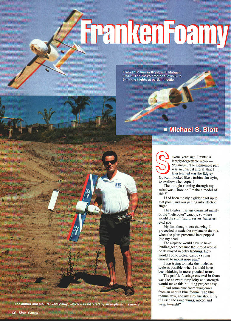
My first flight with the model was in a large rectangle, with control input only at the turns. The 7.2-volt motor will give 6- to 8-minute flights at partial throttle. A 6-volt motor will be faster but will have shorter run times.
Landing is straightforward. Bring the model in line with the landing area at roughly a 10-foot altitude, then cut the motor. Your airplane will have a gentle glide that is not too steep, and it will slow to a landing in 30–40 feet.
Thanks to Dereck Woodward, who pushed me to share the FrankenFoamy, and to my girlfriend Gina, who helped with the movies and pictures.
Michael S. Blott <REDACTED> <REDACTED>
Sources
- FrankenFoamy Wing Set
$10 per wing set + $4 S&H (for as many as three wings) Send check or money order to: Pat Mattes <REDACTED>
Transcribed from original scans by AI. Minor OCR errors may remain.

