
I HAD PROMISED to have the newly re-refitted electric-powered
Genesis Extreme test-flown by the time this column was due, and I
almost made it. Apologies all around for not hitting my target date for
this project; a back issue threw a painful monkey wrench into my
schedule! Before being sidelined, I was able to do a bit more work on
the retrofit.
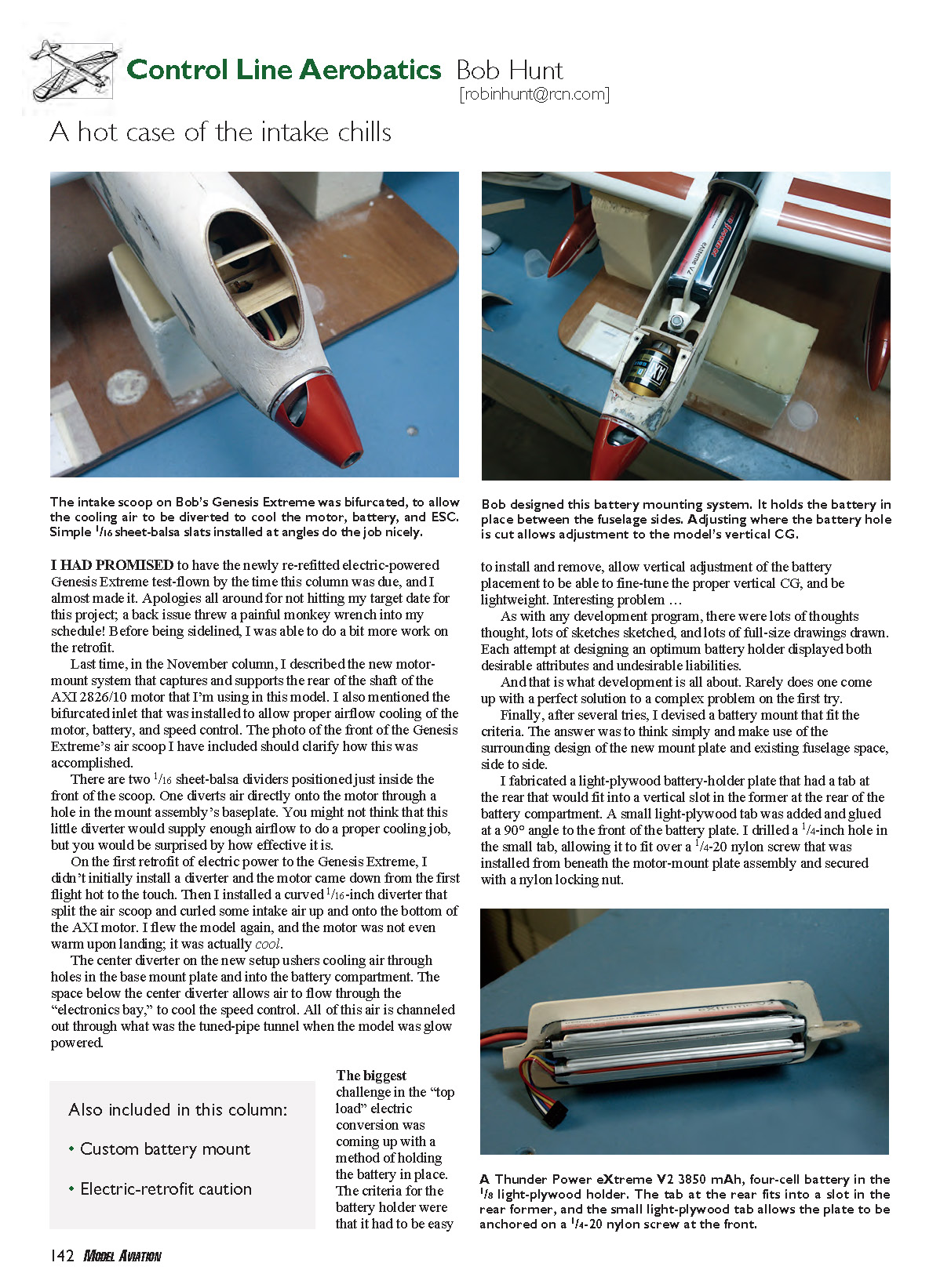
Last time, in the November column, I described the new motormount
system that captures and supports the rear of the shaft of the
AXI 2826/10 motor that I’m using in this model. I also mentioned the
bifurcated inlet that was installed to allow proper airflow cooling of the
motor, battery, and speed control. The photo of the front of the Genesis
Extreme’s air scoop I have included should clarify how this was
accomplished.
There are two 1/16 sheet-balsa dividers positioned just inside the
front of the scoop. One diverts air directly onto the motor through a
hole in the mount assembly’s baseplate. You might not think that this
little diverter would supply enough airflow to do a proper cooling job,
but you would be surprised by how effective it is.
On the first retrofit of electric power to the Genesis Extreme, I
didn’t initially install a diverter and the motor came down from the first
flight hot to the touch. Then I installed a curved 1/16-inch diverter that
split the air scoop and curled some intake air up and onto the bottom of
the AXI motor. I flew the model again, and the motor was not even
warm upon landing; it was actually cool.
The center diverter on the new setup ushers cooling air through
holes in the base mount plate and into the battery compartment. The
space below the center diverter allows air to flow through the
“electronics bay,” to cool the speed control. All of this air is channeled
out through what was the tuned-pipe tunnel when the model was glow
powered. The biggest
challenge in the “top
load” electric
conversion was
coming up with a
method of holding
the battery in place.
The criteria for the
battery holder were
that it had to be easy
to install and remove, allow vertical adjustment of the battery
placement to be able to fine-tune the proper vertical CG, and be
lightweight. Interesting problem …
As with any development program, there were lots of thoughts
thought, lots of sketches sketched, and lots of full-size drawings drawn.
Each attempt at designing an optimum battery holder displayed both
desirable attributes and undesirable liabilities.
And that is what development is all about. Rarely does one come
up with a perfect solution to a complex problem on the first try.
Finally, after several tries, I devised a battery mount that fit the
criteria. The answer was to think simply and make use of the
surrounding design of the new mount plate and existing fuselage space,
side to side.
I fabricated a light-plywood battery-holder plate that had a tab at
the rear that would fit into a vertical slot in the former at the rear of the
battery compartment. A small light-plywood tab was added and glued
at a 90° angle to the front of the battery plate. I drilled a 1/4-inch hole in
the small tab, allowing it to fit over a 1/4-20 nylon screw that was
installed from beneath the motor-mount plate assembly and secured
with a nylon locking nut.
fiberglass arrow shaft over the 1/4-20 nylon
bolt, and that supplied a resting point for the
tab on the battery plate. The length of that
piece of arrow shaft determines the height of
the front of the battery.
Once the plate was installed, a nylon
wing nut could be threaded onto the 1/4-20
nylon bolt, and the plate would be held
secure. (The photos show a metal nut,
because that’s all I had at the time.)
I cut out the light-plywood battery-mount
plate to allow the battery to be installed from
the side with a slight press fit. The battery—
a Thunder Power RC eXtreme V2 3850
mAh, four-cell unit—would sit in the
horizontal position between the fuselage
sides.
The fact that the fuselage is narrow
prevents the battery from cocking from side
to side under load. I will add a minute
rubber bumper on the outboard side of the
battery, to ensure that it will not twist in the
plywood mounting plate, and apply a couple
of small, short beads of clear acrylic glue
where the battery contacts the plywood
mounting plate.
The really nice feature of this mounting
system is that the battery’s vertical
placement can be adjusted by making
several plates with the opening for the
battery in different places in respect to the
motor’s thrustline. All you need to do is testfly
the airplane with the battery at different
vertical positions until you determine which
one is best, and then duplicate that plate as
many times as required to accommodate all
the batteries you intend to use in that model.
It may sound complicated, but a look at
the accompanying photos should clarify the
battery mounting system.
If you are going to use the preceding
system in an aircraft with a wider-than-
normal fuselage, you might have to make
two battery mounting plates and center the
battery between them, to prevent it from
cocking from side to side under load. In
that case, you would need to make two
vertical slots in the aft former, to accept
the two separate tabs on the battery mount
plates. It would be a bit heavier but would
retain the attributes of speed of
installation/removal and adjustability.
To achieve a proper CG location when
using a relatively long battery—such as
the Thunder Power eXtreme V2 3850 mAh
unit—you may have to relieve the LE of
the wing fairly far aft toward the bellcrank
mount and the spar system of the typical
CL Precision Aerobatics (Stunt) model.
You might have to rethink the design of
the wing if you are relying on the inherent
monocoque structure of a “D-tube” or “Ctube”
LE, to provide adequate strength
from breaking.
I was able to chop out much of this
material from my C-tube wing design in
the Genesis Extreme, because I install
robust basswood “tension” and
“compression” joiners aft of the spar
structure on my designs. I don’t rely on
the LE tube structure to provide the
bending/breaking strength at that point.
This is important and should be
considered before attempting a retrofit of
144 MODEL AVIATION
GRAPHLITE High Performance
Carbon Rods & Strips
67% Carbon Fiber – No Fillers
Optimal Fiber Orientation
Conforms to Curves without Wrinkles
Twice the Stiffness of Aluminum
CST carries over 100 sizes of rods, tubes and strips including DPP and standard.
Visit our website at
www.cstsales.com
Order Desk
CST–The Composites Store, Inc. 800-338-1278
Compared to wet tow lay-up:
350% Stronger in Tension
550% Stronger in Compression
an electric system to a previously glowpowered
model.
In a future column, I’ll describe and
illustrate this tension and compression
joiner system. It can be used on glow- or
electric-powered models and allows a glow
airplane’s fuel tank to be set very far aft
into the wing, for balancing purposes. It
also doubles as the bellcrank mount.
Till next time, fly Stunt!