
Click On!
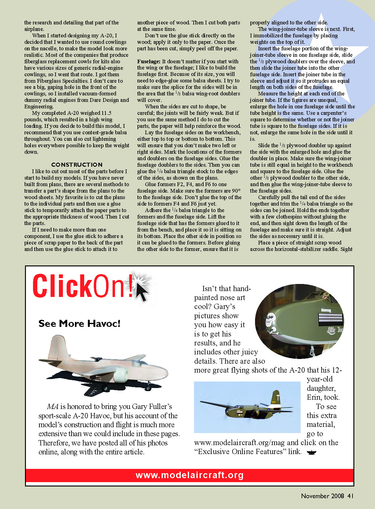
See More Havoc!
MA is honored to bring you Gary Fuller’s sport-scale A-20 Havoc, but his account of the model’s construction and flight is much more extensive than we could include in these pages. Therefore, we have posted all of his photos online, along with the entire article.
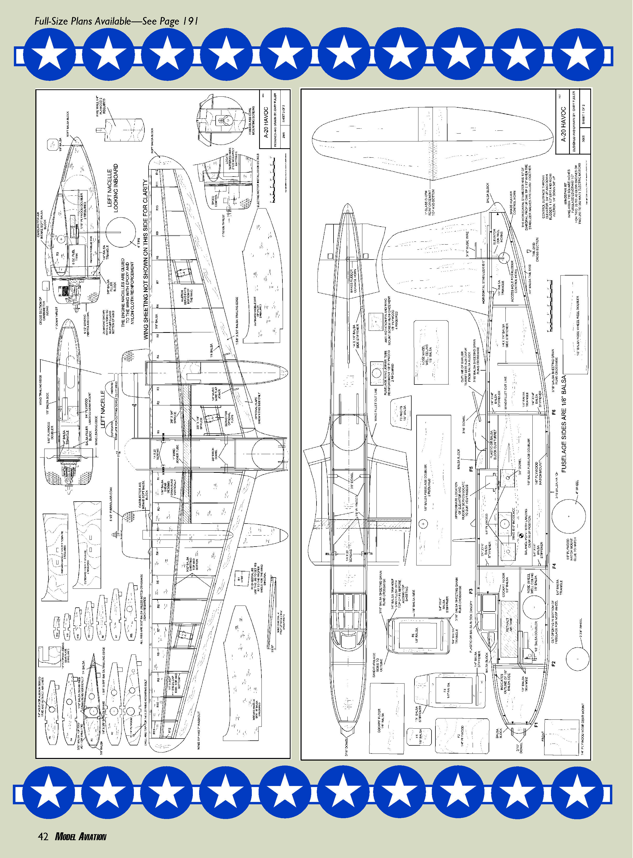
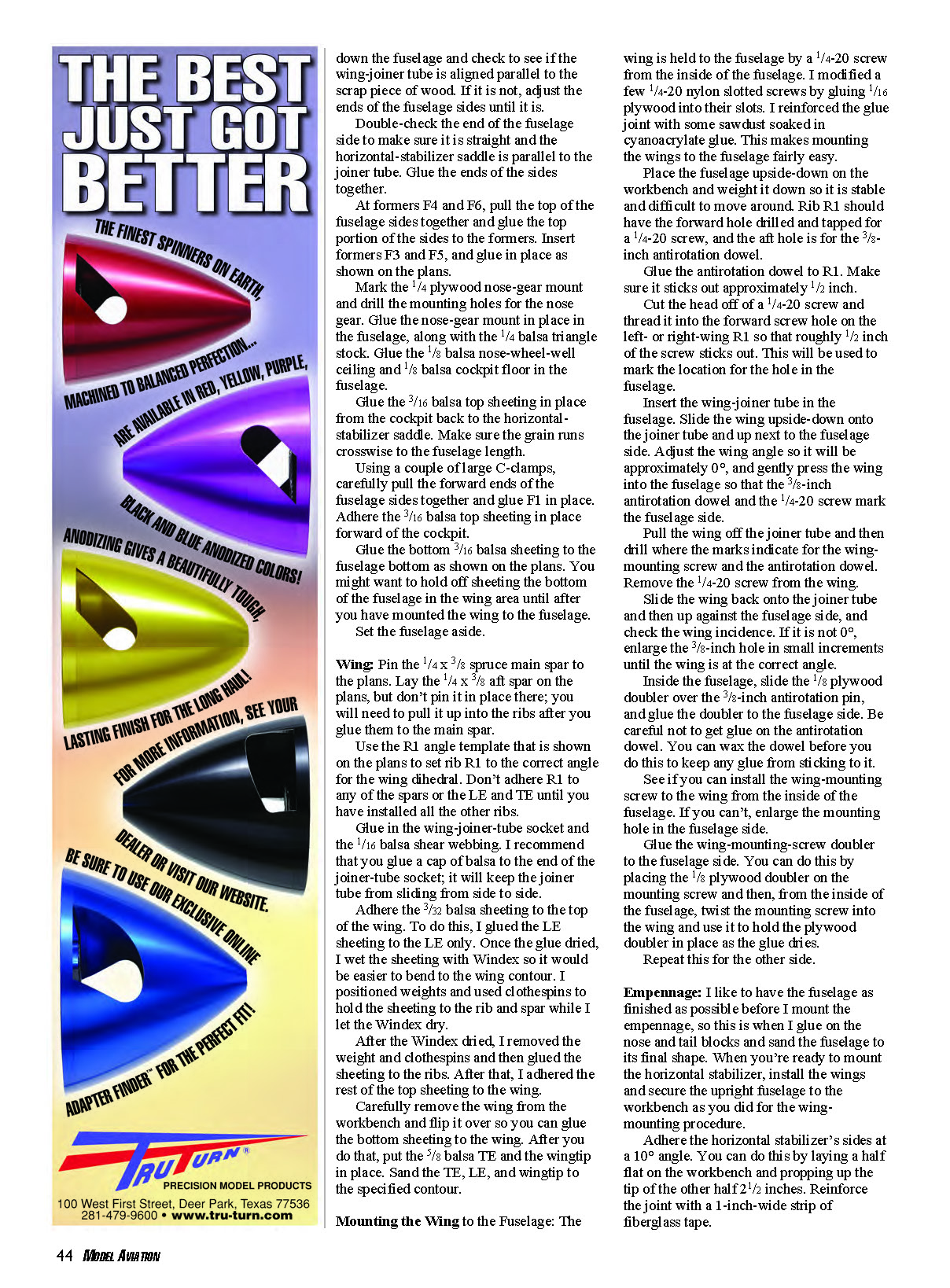
Isn’t that hand-painted nose art cool? Gary’s pictures show you how easy it is to get his results, and he includes other juicy details. There are also more great flying shots of the A-20 that his 12-year-old daughter, Erin, took. To see this extra material, go to www.modelaircraft.org/mag and click on the “Exclusive Online Features” link.
www.modelaircraft.org (No additional article text appears on this page.)
Down the fuselage and check to see if the wing-joiner tube is aligned parallel to the scrap piece of wood. If it is not, adjust the ends of the fuselage sides until it is.
Double-check the end of the fuselage side to make sure it is straight and the horizontal-stabilizer saddle is parallel to the joiner tube. Glue the ends of the sides together.
At formers F4 and F6, pull the top of the fuselage sides together and glue the top portion of the sides to the formers. Insert formers F3 and F5, and glue in place as shown on the plans.
Mark the 1/4 plywood nose-gear mount and drill the mounting holes for the nose gear. Glue the nose-gear mount in place in the fuselage, along with the 1/4 balsa triangle stock. Glue the 1/8 balsa nose-wheel-well ceiling and 1/8 balsa cockpit floor in the fuselage.
Glue the 3/16 balsa top sheeting in place from the cockpit back to the horizontal-stabilizer saddle. Make sure the grain runs crosswise to the fuselage length.
Using a couple of large C-clamps, carefully pull the forward ends of the fuselage sides together and glue F1 in place. Adhere the 3/16 balsa top sheeting in place forward of the cockpit.
Glue the bottom 3/16 balsa sheeting to the fuselage bottom as shown on the plans. You might want to hold off sheeting the bottom of the fuselage in the wing area until after you have mounted the wing to the fuselage.
Set the fuselage aside.
Wing: Pin the 1/4 x 3/8 spruce main spar to the plans. Lay the 1/4 x 3/8 aft spar on the plans, but don't pin it in place there; you will need to pull it up into the ribs after you glue them to the main spar.
Use the R1 angle template that is shown on the plans to set rib R1 to the correct angle for the wing dihedral. Don't adhere R1 to any of the spars or the LE and TE until you have installed all the other ribs.
Glue in the wing-joiner-tube socket and the 1/16 balsa shear webbing. I recommend that you glue a cap of balsa to the end of the joiner-tube socket; it will keep the joiner tube from sliding from side to side.
Adhere the 3/32 balsa sheeting to the top of the wing. To do this, I glued the LE sheeting to the LE only. Once the glue dried, I wet the sheeting with Windex so it would be easier to bend to the wing contour. I positioned weights and used clothespins to hold the sheeting to the rib and spar while I let the Windex dry.
After the Windex dried, I removed the weight and clothespins and then glued the sheeting to the ribs. After that, I adhered the rest of the top sheeting to the wing.
Carefully remove the wing from the workbench and flip it over so you can glue the bottom sheeting to the wing. After you do that, put the 5/8 balsa TE and the wingtips in place. Sand the TE, LE, and wingtip to the specified contour.
Mounting the Wing to the Fuselage: The wing is held to the fuselage by a 1/4-20 screw from the inside of the fuselage. I modified a few 1/4-20 nylon slotted screws by gluing 1/16 plywood into their slots. I reinforced the glue joint with some sawdust soaked in cyanoacrylate glue. This makes mounting the wings to the fuselage fairly easy.
Place the fuselage upside-down on the workbench and weight it down so it is stable and difficult to move around. Rib R1 should have the forward hole drilled and tapped for a 1/4-20 screw, and the aft hole is for the 3/8-inch antirotation dowel.
Glue the antirotation dowel to R1. Make sure it sticks out approximately 1/2 inch.
Cut the head off of a 1/4-20 screw and thread it into the forward screw hole on the left- or right-wing R1 so that roughly 1/2 inch of the screw sticks out. This will be used to mark the location for the hole in the fuselage.
Insert the wing-joiner tube in the fuselage. Slide the wing upside-down onto the joiner tube and up next to the fuselage side. Adjust the wing angle so it will be approximately 0°, and gently press the wing into the fuselage so that the 3/8-inch antirotation dowel and the 1/4-20 screw mark the fuselage side.
Pull the wing off the joiner tube and then drill where the marks indicate for the wing-mounting screw and the antirotation dowel. Remove the 1/4-20 screw from the wing.
Slide the wing back onto the joiner tube and then up against the fuselage side, and check the wing incidence. If it is not 0°, enlarge the 3/8-inch hole in small increments until the wing is at the correct angle.
Inside the fuselage, slide the 1/8 plywood doubler over the 3/8-inch antirotation pin, and glue the doubler to the fuselage side. Be careful not to get glue on the antirotation dowel. You can wax the dowel before you do this to keep any glue from sticking to it.
See if you can install the wing-mounting screw to the wing from the inside of the fuselage. If you can't, enlarge the mounting hole in the fuselage side.
Glue the wing-mounting-screw doubler to the fuselage side. You can do this by placing the 1/8 plywood doubler on the mounting screw and then, from the inside of the fuselage, twist the mounting screw into the wing and use it to hold the plywood doubler in place as the glue dries.
Repeat this for the other side.
Empennage: I like to have the fuselage as finished as possible before I mount the empennage, so this is when I glue on the nose and tail blocks and sand the fuselage to its final shape. When you're ready to mount the horizontal stabilizer, install the wings and secure the upright fuselage to the workbench as you did for the wing-mounting procedure.
Adhere the horizontal stabilizer's sides at a 10° angle. You can do this by laying a half flat on the workbench and propping up the tip of the other half 2 1/2 inches. Reinforce the joint with a 1-inch-wide strip of fiberglass tape.
Click On!
Mount the power plants to the nacelles. Then using each motor’s propeller shaft, bolt it to the angle in the holes you drilled. Now both power plants are aligned to each other. That is crucial: since the nacelles don’t need to be aligned to each other, the engines’ thrustlines do.
Place the wing in the wing saddle of the nacelles. Adjust the wing in the saddles so that the inside side of the nacelles is approximately 7 inches from the edge of the wing root. Do not adjust the gap between the wings. If you measured accurately, both nacelles should be this length from the root rib. If the measurement is not the same on both wings, move the wing until it is.
Employ an incidence meter to check the engine upthrust/downthrust line in relationship to the wing incidence. Sand the nacelle saddles so that the thrustline is -1°. Once you are satisfied with all these measurements, tack-glue the nacelles to the wings.
Carefully unbolt the motors from the aluminum angle, and then separate the wings from each other. Flip the wings over so you can glue the nacelles to them with epoxy and glass cloth on the inside of the nacelles.
I like to mount the retracts, servos, and linkages before I cover my models. I used one servo for the elevators using a Y-type pushrod. If you do this, make sure it is as stiff as possible. You can also use two servos to control the elevators. The rest of the radio installation is fairly straightforward, so use your best judgment as a guide.
I used a pair of MaxCim MaxN32-13Y motors geared 2.2:1 swinging 14 x 8.5 APC electric propellers. Two 4S2P Li-Poly batteries supply the power. The speed controls are attached to the firewalls with hook-and-loop fastener, and the batteries are mounted just behind the firewall in each nacelle.
Flying: With the high wing loading the A-20 has, don’t yank it off the runway as soon as possible. Give it a nice, long run, and ease it off the runway by gradually applying up-elevator until it rotates and lifts off on its own. For landings, keep the speed up and carry a little power on the final approach.
You can make nice, main-wheel-first touchdowns with a nice rollout before the nose wheel settles to the runway. The plans show optional flaps, but I did not install them on my A-20. My friend, Gary Scott, installed them on his model, and he reports that they are extremely effective. With motors, the propellers will create a lot of drag when power is reduced and they freewheel.
I have no idea how the A-20 will behave with one motor dead in-flight. When rudder is applied, the airplane will roll in the direction of the rudder and the nose will drop. I think the nose’s dropping is caused by the 10° of dihedral in the horizontal stabilizer. The strong rudder authority should be a benefit if a motor ever quits.
If you have no twin-engine-model flying experience, make sure you set up the motors so that they are reliable. Don’t try to get every extra bit of power out of them; set them for reliability. Set up the motors one at a time. Resist the urge to synchronize them; they only need to be close.
I don’t do a great deal of aerobatics with my model, but I have made it loop, roll, and fly inverted. I’m pleased with my A-20; it looks good in the air and I like how it flies. MA
Gary Fuller gfuller@dishmail.net
Sources:
- MonoKote
(800) 637-7660 www.monokote.com
- Fiberglass Specialties
(479) 359-2429 www.fiberglassspecialtiesinc.com
- Dare Design and Engineering
(800) 578-3273 www.darehobby.com
- MaxCim Motors
(716) 662-5651 www.maxcim.com
- APC Propellers
(530) 661-0399 www.apcprop.com
Transcribed from original scans by AI. Minor OCR errors may remain.

