
AIR BEAR
DOESN'T COST MUCH. NOT TOO HARD TO BUILD. FUN TO FLY. GOOD REASONS TO GET A BEAR IN THE AIR!
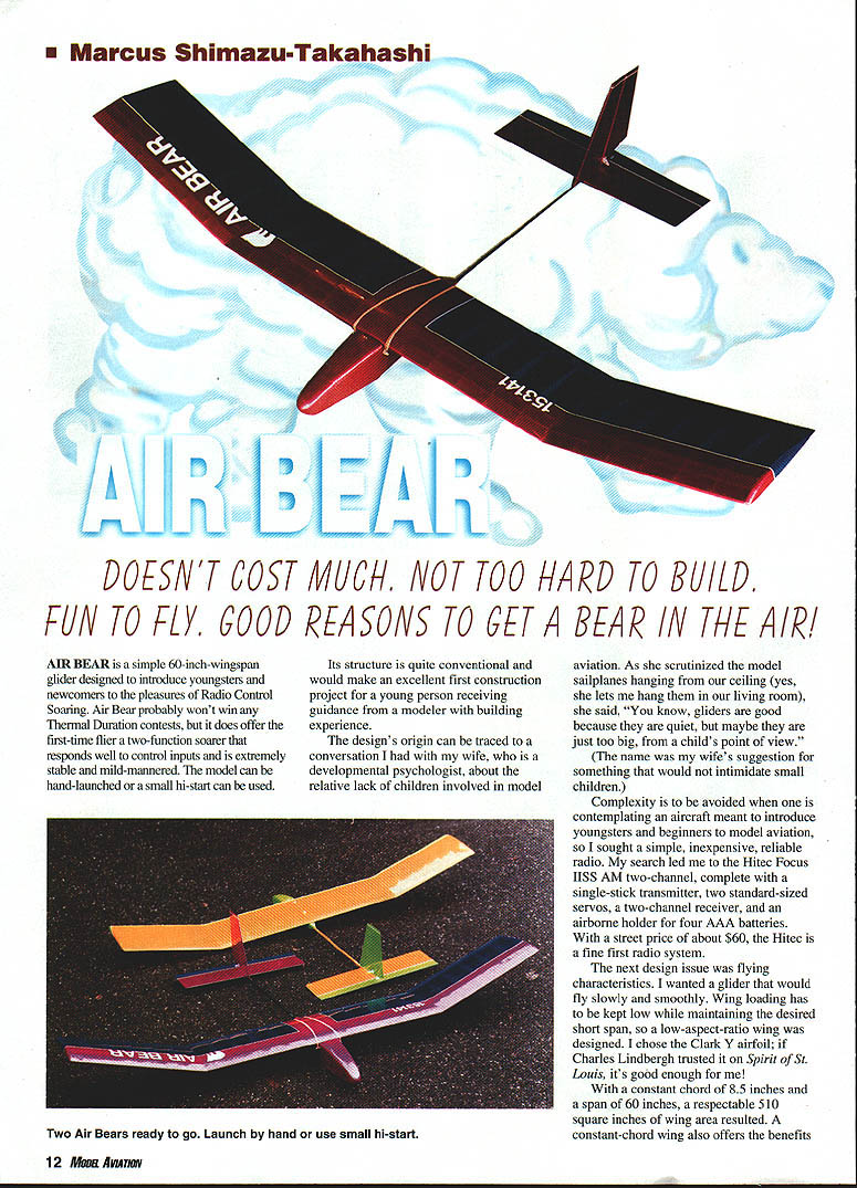
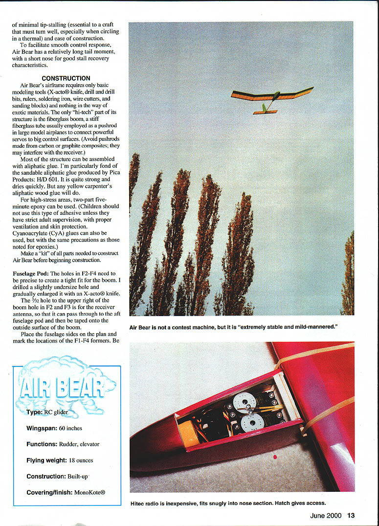
Air Bear is a simple 60-inch-wingspan glider designed to introduce youngsters and newcomers to the pleasures of Radio Control Soaring. Air Bear probably won't win any Thermal Duration contests, but it does offer the first-time flier a two-function soarer that responds well to control inputs and is extremely stable and mild-mannered. The model can be hand-launched or a small hi-start can be used.
Its structure is quite conventional and would make an excellent first construction project for a young person receiving guidance from a modeler with building experience.
The designer's origin can be traced to a conversation I had with my wife, who is a developmental psychologist, about the relative lack of children involved in model aviation. As she scrutinized the model sailplanes hanging from our ceiling (yes, she lets me hang them in our living room), she said, "You know, gliders are good because they are quiet, but maybe they are just too big, from a child's point of view." (The name was my wife's suggestion for something that would not intimidate small children.)
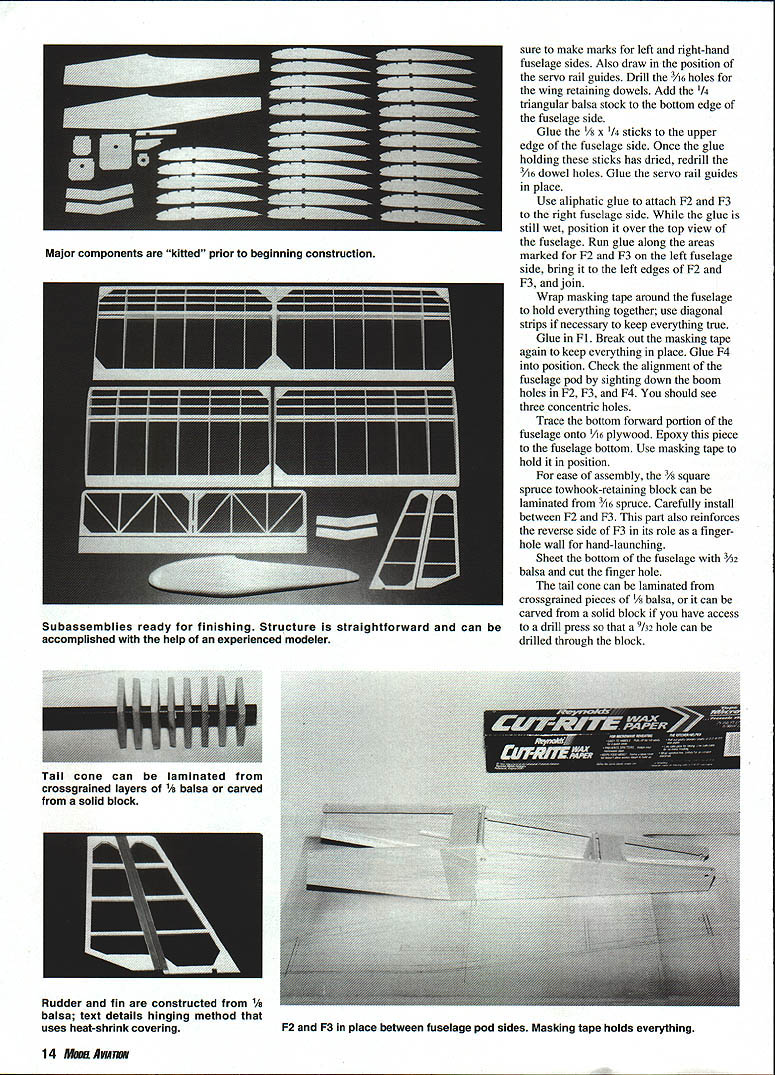
Complexity is to be avoided when one is contemplating an aircraft meant to introduce youngsters and beginners to model aviation, so I sought a simple, inexpensive, reliable radio. My search led me to the Hitec Focus IISS AM two-channel, complete with a single-stick transmitter, two standard-sized servos, a two-channel receiver, and an airborne holder for four AAA batteries. With a street price of about $60, the Hitec is a fine first radio system.
The next design issue was flying characteristics. I wanted a glider that would fly slowly and smoothly. Wing loading has to be kept low while maintaining the desired short span, so a low-aspect-ratio wing was designed. I chose the Clark Y airfoil; if Charles Lindbergh trusted it on Spirit of St. Louis, it's good enough for me!
With a constant chord of 8.5 inches and a span of 60 inches, a respectable 510 square inches of wing area resulted. A constant-chord wing also offers the benefits of minimal tip-stalling (essential to a craft that must turn well, especially when circling in a thermal) and ease of construction.
To facilitate smooth control response, Air Bear has a relatively long tail moment, with a short nose for good stall recovery characteristics.
Specifications
- Type: RC glider
- Wingspan: 60 inches
- Functions: Rudder, elevator
- Flying weight: 18 ounces
- Construction: Built-up
- Covering/finish: MonoKote®
CONSTRUCTION
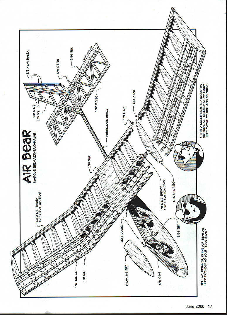
Air Bear's airframe requires only basic modeling tools: X-acto® knife, drill and bits, rulers, soldering iron, wire cutters, and sanding blocks. Nothing exotic is needed. The only "hi‑tech" part is the fiberglass boom, a stiff fiberglass tube usually employed as a pushrod in large model airplanes to connect powerful servos to big control surfaces. (Avoid pushrods made from carbon or graphite composites; they may interfere with the receiver.)
Most of the structure can be assembled with aliphatic glue. I'm particularly fond of the sandable aliphatic glue produced by Pica Products: HI‑D 601. It is quite strong and dries quickly. But any yellow carpenter's aliphatic wood glue will do.
For high‑stress areas, two‑part five‑minute epoxy can be used. (Children should not use this type of adhesive unless they have strict adult supervision, with proper ventilation and skin protection.)
Cyanoacrylate (CyA) glues can also be used, but with the same precautions as those noted for epoxies.
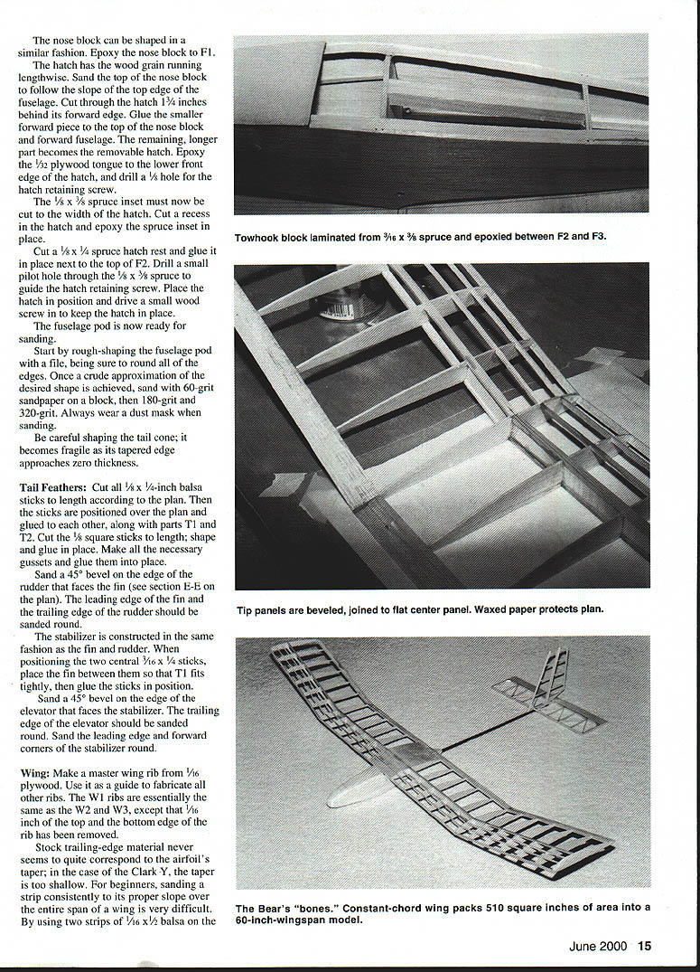
Make a "kit" of all parts needed to construct Air Bear before beginning construction.
Fuselage Pod
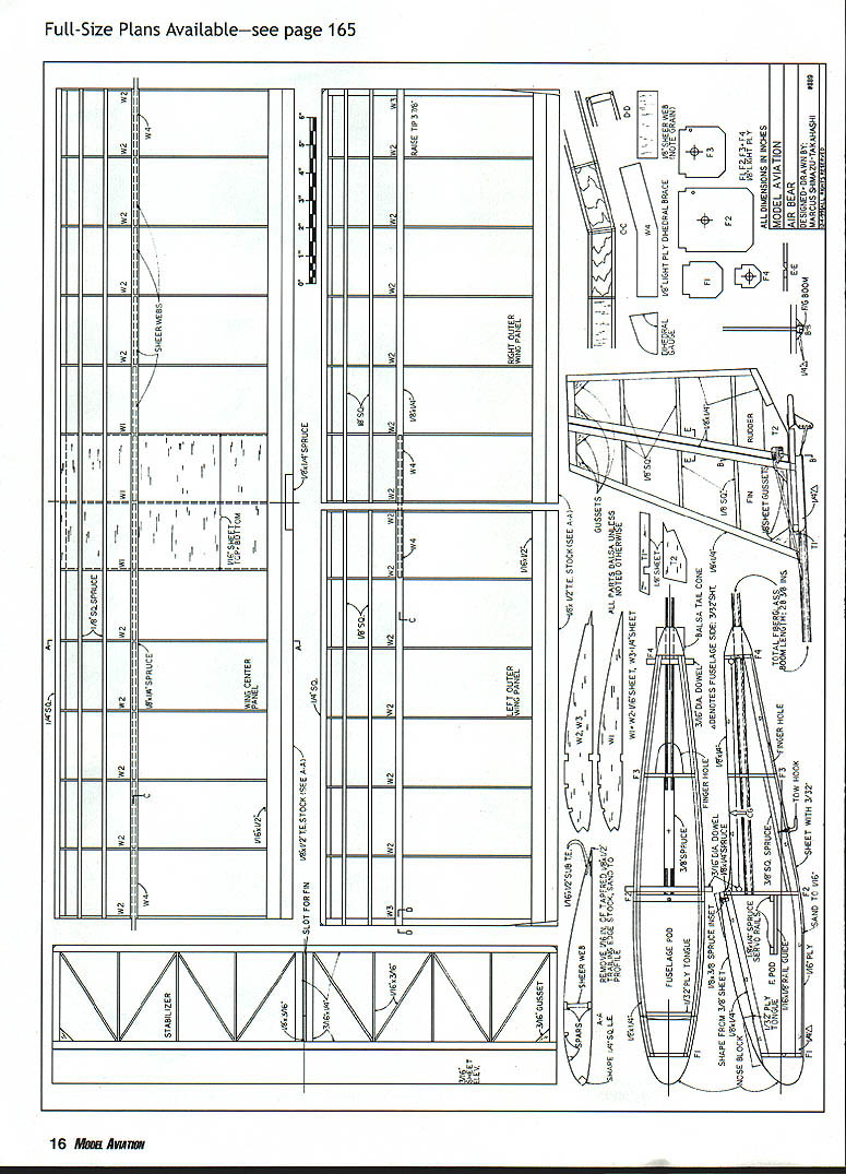
- The holes in formers F2–F4 need to be precise to create a tight fit for the boom. Drill a slightly undersize hole first and gradually enlarge it with an X‑acto® knife for a snug fit.
- The 3/32-inch hole to the upper right of the boom hole in F2 and F3 is for the receiver antenna, so it can pass through to the aft fuselage pod and then be taped onto the outside surface of the boom.
- Place the fuselage sides on the plan and mark the locations of formers F1–F4. Make marks for left and right fuselage sides and draw in the position of the servo rail guides.
- Drill the 3/16-inch holes for the wing retaining dowels. Add 1/4-inch triangular balsa stock to the bottom edge of the fuselage side.
- Glue 1/8 x 1/4 sticks to the upper edge of the fuselage side. Once dry, redrill the 3/16 dowel holes and glue the servo rail guides in place.
- Use aliphatic glue to attach F2 and F3 to the right fuselage side. While the glue is still wet, position the assembly over the top view of the fuselage, apply glue to the corresponding areas on the left fuselage side, and join.
- Wrap masking tape around the fuselage to hold everything together; use diagonal strips if necessary to keep everything true.
- Glue in F1, then F4. Check alignment by sighting down the boom holes in F2, F3, and F4 — you should see three concentric holes.
- Trace the bottom forward portion of the fuselage onto 1/16 plywood and epoxy this piece to the fuselage bottom, holding it with masking tape while the epoxy sets.
- Laminate the 3/8-inch square spruce towhook‑retaining block from 3/16 spruce and install it carefully between F2 and F3. This part also reinforces the reverse side of F3 as a finger‑hole wall for hand‑launching.
- Sheet the bottom of the fuselage with 3/32 balsa and cut the finger hole.
- The tail cone can be laminated from cross‑grained pieces of 1/8 balsa or carved from a solid block; drill a 3/32 hole through the block if carving.
- Shape the nose block similarly and epoxy it to F1.
Hatch
- The hatch has the wood grain running lengthwise. Sand the top of the nose block to follow the slope of the top edge of the fuselage.
- Cut through the hatch 1 3/4 inches behind its forward edge. Glue the smaller forward piece to the top of the nose block and forward fuselage. The remaining longer part becomes the removable hatch.
- Epoxy a 1/32 plywood tongue to the lower front edge of the hatch and drill a 1/8-inch hole for the hatch retaining screw.
- Cut a 1/8 x 3/8 spruce inset to the hatch width, cut a recess in the hatch, and epoxy the spruce inset in place.
- Cut a 1/8 x 1/4 spruce hatch rest and glue it in place next to the top of F2. Drill a small pilot hole through the 1/8 x 3/8 spruce to guide the hatch retaining screw. Place the hatch and drive a small wood screw to keep it in place.
Sanding the Pod
- Rough‑shape the fuselage pod with a file, rounding all edges. Progress through 60‑, 180‑, and 320‑grit sandpaper on a block. Always wear a dust mask when sanding.
- Be careful shaping the tail cone; it becomes fragile as its tapered edge approaches zero thickness.
Tail Feathers
- Cut all 1/8 x 1/4‑inch balsa sticks to length according to the plan. Position the sticks over the plan and glue them together along with parts T1 and T2.
- Cut the 1/8 square sticks to length; shape and glue in place. Make all necessary gussets and glue them in place.
- Sand a 45° bevel on the edge of the rudder that faces the fin (see section E–E on the plan). Sand the leading edge of the fin and the trailing edge of the rudder round.
- Construct the stabilizer in the same fashion as the fin and rudder. When positioning the two central 1/16 x 1/4 sticks, place the fin between them so that T1 fits tightly, then glue the sticks in position.
- Sand a 45° bevel on the edge of the elevator that faces the stabilizer. Sand the trailing edge of the elevator round, and sand the leading edge and forward corners of the stabilizer round.
Wing
- Make a master wing rib from 1/16 plywood and use it as a guide to fabricate the other ribs. The W1 ribs are essentially the same as W2 and W3, except that 1/16 inch of the top and bottom edge of the rib has been removed.
- Note: stock trailing‑edge material often does not match the airfoil’s taper; sanding a single strip consistently to the proper slope over the entire span can be difficult. (Full construction details and full‑size plans/illustrations are provided on the original plans.)
Boom, Pushrods, and Control Linkage
- When installing sheaths down the elevator area in the boom, you can insert a length of 1/32 music wire into the sheath while the CyA dries; excess glue will run out the lower end of the boom — let it drip onto a paper towel.
- Apply epoxy to the ends of the boom to close it up and keep the ends of the sheaths in place. Apply a drop of epoxy to the exit point of the rudder pushrod sheath from the boom. Trim the yellow sheaths at the tail end of the boom.
- Attach Goldberg mini‑control horns to the rudder and elevator. Cut away excess length of the retaining screws on the horns and carefully file the screw ends flush with the retaining plate on the other side of the horn.
- To minimize slop in thin cable pushrods, solder 1/16 OD brass tubes over the ends of the cables. Heat the end of the brass tube/cable and make a Z‑bend with needle‑nose pliers. Between the solder and the Z‑bend, the brass tube and cable become inseparable.
- Make the triangle‑stock rails that attach to the bottom of the stabilizer; round their front ends. Cover the long side with MonoKote® only.
- Place the boom on the bottom surface of the stabilizer and center it. Position the triangle rails along the boom, noting the boom stops an inch short of the elevator hinge.
- Remove covering from the bottom surface of the stabilizer where it contacts the triangle stock rails and the boom. Apply glue to the bare wood of the rails, attach to the bare wood of the stabilizer, and use the boom to accurately space them.
- Let glue dry, then epoxy the stabilizer onto the boom. Ensure the rudder pushrod sheath is in the proper position.
- Cut away MonoKote® that covers the slot for the fin on the upper surface of the stabilizer. Remove covering on the lower edge of the fin where it slips into the stabilizer slot and test the fit. Glue the lower fin into the slot and use a right angle to ensure the fin is perpendicular to the stabilizer.
Servo Installation and Final Assembly
- Cut the spruce servo rails to length and epoxy them in position using installed servo guides as reference. Install the servos.
- Slide the boom into the fuselage pod until its end is flush with the side of F2 that faces the servos. It should be a tight fit.
- Accurately position the wing onto the fuselage pod using rubber bands. With the airplane on a table and viewing from the front, check that the stabilizer is parallel to the wing center section. Twist the boom if necessary. Once set, remove the wing and apply epoxy to all areas where the boom contacts F2, F3, and F4.
- Hook up your radio control system. Remove servo wheels (arms), connect airborne components, and install Goldberg pushrod connectors on servo wheels for fine adjustment.
- On the left servo position the connector at about the 3 o'clock position (about 1/4 inch from the nose); on the right servo position the connector at 9 o'clock.
- Run the yellow pushrod sheaths by the pushrod connectors and measure 1/2 inch from the connector back toward the boom. Trim the sheaths to this point.
- Connect the Z‑bend ends of the pushrods to the rudder and elevator control horns, then slide the other ends into the sheaths from the back end. The rudder linkage should connect at the second hole out from the rudder; the elevator should connect at the third hole out from the elevator. The free ends of the pushrod cables will emerge next to the pushrod connectors.
- Move rudder and elevator to their neutral positions. Measure 1/2 inch past the connector toward the nose on the pushrod and cut the pushrods at this point. Remove servo wheels from the servos.
- Cut two lengths of 1/16 OD brass tube 5/8 inch long and solder them onto the pushrod cables as done for the rudder and elevator linkage. Bend a slight kink in the brass tube for added security.
- Slide the pushrod connectors onto the brass tubes, but do not tighten. Reconnect servo wheels, ensuring correct positions, and drive the black servo wheel retaining screws back in place.
- Position elevator and rudder neutral, straighten the pushrods, and tighten the pushrod connector retaining screws. Apply a drop of Loctite® if desired.
- Make a towhook by rebending a common brass cup hook to the shape shown on the plan. Drill a pilot hole through the bottom of the fuselage pod into the spruce towhook‑retaining block and screw the towhook in place.
- Wrap the receiver in thin foam and install fresh batteries in the holder. Run the receiver antenna through the holes in F2 and F3, drill a small hole at the rear of the fuselage pod about 1/2 inch below the wing retaining dowel, run the antenna out, and tape it to the outside of the boom all the way to the tail.
- Turn on the transmitter and airborne system and check for proper movement of the control surfaces.
- Put the receiver and batteries back in the pod and screw down the hatch.
Balancing and Trim
- Check the model’s balance by placing your index fingers beneath the spar of the center section. If the tail tilts down, add weight to the nose. If the nose tilts down, add weight to the tail.
- Place one finger beneath the nose and one beneath the end of the boom to determine if one side of the wing is heavier. Add weight to the lighter side as needed.
FLYING AND MAINTENANCE
- Air Bear is quite docile and should be flown only on calm days when the wind is less than 10 miles per hour.
- Check that your model is balanced at the correct spot and always range‑test your radio system before flying.
- Use at least six new rubber bands (three on each side) to hold down the wing. Check the fiberglass boom for cracks.
- Before every flight, perform a complete walkaround inspection. Ensure batteries are fresh or fully charged.
- Initial flights should be over grass. A firm toss into the wind will suffice to get the glider going. Make small adjustments to glide angle using the transmitter trim levers.
- A small hi‑start can get your Air Bear aloft quickly; a touch of up‑elevator will produce a steep climb. With practice you’ll notice the telltale wing waggle indicating a thermal might be present.
Enjoy your Air Bear!
MA Marcus Shimazu‑Takahashi 2275 Lake Whatcom Blvd., PMB‑161 Bellingham, WA 98226‑2777 Starbjorn@aol.com
Transcribed from original scans by AI. Minor OCR errors may remain.

